iManager NetEco 6000
Device Installation and Commissioning Guide
4 Connecting Monitoring Cables to Devices
Issue 03 (2019-03-10)
Copyright © Huawei Technologies Co., Ltd.
86
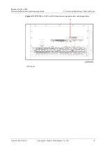
Silk Screen
Port Description
AI/DI_1,
AI/DI_2,
AI/DI_3, and
AI/DI_4
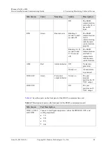
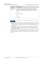
Provide 12 V DC outputs for sensors and are compatible with 4 mA to
20 mA current signals, signals from current-based smoke sensors and
water sensors, dry contact signals, and NTC signals.
Pin definition:
3: 12 V DC, 54 mA
6: D-
7: D+
8: GND
Do not connect an active sensor to an AI/DI port. Otherwise, the port will be invalid.
Sensors including 4 mA to 20 mA sensors, door status sensors, water sensors, and smoke sensors
provide data for the ports.
The power supply of each AI/DI port can be separately controlled. Each port provides a maximum of
14.6 V, 54 mA output power.
4.3.3 Connecting a Monitoring Cable to an Independent
Deployment AI/DI Unit
Prerequisites
A network cable used for monitoring is prepared.
Procedure
Step 1
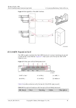
Connect one end of the network cable to the COM_IN port on the independent deployment
AI/DI unit.
Step 2
Connect the other end of the network cable to the COM port with 12 V power supply on the
collector, namely COM4 or COM5 port.
Step 3
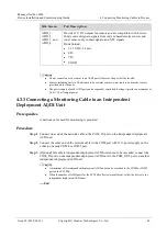
(Optional) If multiple independent deployment AI/DI units need to be cascaded, connect the
COM_IN port on one independent deployment AI/DI unit to the COM_OUT port on another
independent deployment AI/DI unit.
A maximum of two independent deployment AI/DI units can be cascaded to the COM4 or COM5
port on the ECC500.
When the number of AI/DI ports for the ECC500 collector is insufficient, collect the device to the
independent deployment AI/DI unit.
----End

