background image

iManager NetEco 6000 
Device Installation and Commissioning Guide 

5 Checking the Installation 


Issue 03 (2019-03-10) 

Copyright © Huawei Technologies Co., Ltd. 

121 


SN 

Check Item 

The bare wires and OT terminals at the wiring terminals are tightly wrapped up 
with PVC insulation tapes or heat shrink tubing.  

The power cables and ground cables connecting the PDB with each device, and the 
ground cables connecting each device with the PGND busbar of the cabinet are all 
correctly installed and have good contact. 

The power cables and ground cables are bound separately from other cables.   

10 

Labels are attached at both ends of the power cables and ground cables.   

11 

The plastic cover plate on the top of wiring terminals of the PDB is properly 
installed. 


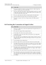
5.4 Checking the Connection of Signal Cables 

SN 

Check Item 

There are no solder joints or connectors in signal cables. The signal cables are not 
scratched or broken. 

The connectors of signal cables are tight and secure. 

Proper length of the cable is reserved at the connectors. 

Proper length is reserved for signal cables at turning points. The turning radius 
meets the requirement. 

The optical fibers must be sheathed using corrugated pipes at outsides of cabinets. 
Both ends of the pipes must be fastened. The edges are smooth or be processed for 
cutting prevention. 

No other cables are laid on optical fibers. 

The extra optical cables are coiled on the cable coiler at the rear of the cabinet. 

The signal cables connected to the left part of the subrack are led out of the subrack 
from the left. Similarly, the signal cables connected to the right part of the subrack 
are led out of the subrack from the right. 

The signal cables are bound separately from the power cables. The signal cables are 
bound and arranged neatly and closely. The cable ties are spaced evenly. The tips 
of the cable ties point to the same direction. 

10 

The extra length of the cable ties must be cut and the cut surface must be smooth. 

11 

The cables whose connectors are far away from the cable entrance are arranged at 
the external side of the cable bundle, while those near the entrance are arranged at 
the internal side of the cable bundle. The trunk cables are laid out smoothly without 
any tangling. 

Содержание iManager NetEco 6000

Страница 1: ...iManager NetEco 6000 V600R008C00 Device Installation and Commissioning Guide Issue 03 Date 2019 03 10 HUAWEI TECHNOLOGIES CO LTD ...

Страница 2: ...stomer All or part of the products services and features described in this document may not be within the purchase scope or the usage scope Unless otherwise specified in the contract all statements information and recommendations in this document are provided AS IS without warranties guarantees or representations of any kind either express or implied The information in this document is subject to ...

Страница 3: ... about NetEco product software commissioning see iManager NetEco 6000 V600R008C00 Product Documentation The figures provided in this document are for reference only The corresponding software version is NetEco V600R008C00SPC310 Intended Audience This document is intended for Sales engineers Technical support personnel System engineers Symbol Conventions The symbols that may be found in this docume...

Страница 4: ...nt issues are cumulative The latest document issue contains all the changes made in earlier issues Issue 03 2019 03 10 Updated the air conditioner name to smart cooling product Updated some MDU screenshots Issue 02 2019 01 10 Modified the Setting Monitoring Parameters for a Hydrogen Sensor section Modified the Adding a Camera on the VCN500 section Modified the alarm names on the alarm renaming pag...

Страница 5: ...switches 18 3 4 Installing an ECC500 ECC800 Collector 19 3 5 Installing an independent deployment AI DI unit 20 3 6 Installing Sensors 20 3 6 1 Installing a NTC Temperature Sensor 20 3 6 2 Installing the Hydrogen Detection System 22 3 6 3 Installing an SDLH 94R Dry Contact type Smoke Detector 24 3 6 4 Installing an Infrared Sensor 25 3 6 5 Installing a WS332M2 5 Ambient Temperature and Humidity Se...

Страница 6: ...onnecting the UPS2000 G Monitoring Cable SNMP 75 4 2 5 2 Connecting the UPS5000G A Monitoring Cable 75 4 2 5 3 Connecting the UPS5000 E or UPS5000 S Monitoring Cable 78 4 2 6 Connecting the PDU8000 Monitoring Cable 78 4 2 7 Connecting a Monitoring Cable to TP483000D 78 4 2 8 Connecting a Monitoring Cable to a CIM01C2 79 4 3 Scenarios for Connecting the ECC500 Collector 79 4 3 1 Preparing a Monitor...

Страница 7: ...ng the Installation 119 5 1 Checking the Installation of the Cabinet 119 5 2 Checking the Installation of Components in the Cabinet 120 5 3 Checking the Installation of Power Cables and Ground Cables 120 5 4 Checking the Connection of Signal Cables 121 6 Adding Devices 122 6 1 Basic Operations Before Adding Devices 123 6 1 1 Creating a Domain 123 6 1 2 Adding a Module 127 6 2 Scenarios for Connect...

Страница 8: ...3 Setting SNMP Parameters for the ECC500 V6 Collector 185 6 4 1 4 Setting RS485 Parameters for the ECC500 V6 Collector 188 6 4 1 5 Creating an ECC500 V6 Collector on the NetEco 190 6 4 2 Adding Sensors 192 6 4 2 1 Adding Dry Contact Interface Devices 192 6 4 2 1 1 Setting Door Status Sensor Monitoring Parameters on the ECC 192 6 4 2 1 2 Setting Smoke Sensor and Water Leakage Sensor Parameters on t...

Страница 9: ...nitoring Parameters for a UPS2000 233 6 4 5 2 Creating a UPS on the NetEco 234 6 4 6 Adding a PDU 236 6 4 6 1 Setting Monitoring Parameters for a PDU8000 236 6 4 6 2 Creating a PDU on the NetEco 237 6 4 7 Adding a RPDU 239 6 4 7 1 Setting Monitoring Parameters for HPXPDU2000 16 3PH 24 6 M1 239 6 4 7 2 Creating a RPDU on the NetEco 240 6 5 Scenarios for Connecting the ECC800 Collector 242 6 5 1 Com...

Страница 10: ...acing an Infrared Sensor 269 7 2 5 5 Replacing a T H Sensor 270 7 2 5 6 Replacing a Region type Water Sensor and Water Detection Cable 270 7 2 5 7 Replacing a Location type Water Sensor and Water Detection Cable 272 7 2 6 Replacing the Management System 273 7 2 6 1 Replacing a VCN500 273 7 2 6 2 Replacing the Hard Disk 275 7 2 6 3 Replacing an IPC6325 Camera 277 7 2 6 4 Replacing an IPC6225 camera...

Страница 11: ...vice Installation and Commissioning Guide Contents Issue 03 2019 03 10 Copyright Huawei Technologies Co Ltd x 8 7 How Can I Commission a Device That Connects Through the ECC500 RS485 Port 305 A Acronyms and Abbreviations 310 ...

Страница 12: ...s which are not specified in related international standards Unauthorized modifications to the product or software code Operations not complying with the operation instructions and safety precautions in this document Device damage due to abnormal natural factors Overview To ensure safety of humans and the equipment pay attention to the safety symbols on the equipment and all the safety instruction...

Страница 13: ... the electrical inspection carefully The device or system must be connected permanently to the protection ground before an operation Before operating the device check the electrical connection of the device to ensure that it is securely grounded Human Safety Before operating a device wear electrostatic discharge ESD clothes ESD gloves and an ESD wrist strap Do not wear jewelry or watches when you ...

Страница 14: ...een the core of the power cable and the conductor may generate electric arcs or sparks which may cause fire or hurt human eyes Before installing or removing the power cable turn off the power switch Before connecting a power cable verify that the label on the power cable is correct Electrostatic Discharge The static electricity generated by human bodies may damage the electrostatic sensitive compo...

Страница 15: ...ies may cause danger When operating batteries avoid short circuits and electrolyte overflow or leakage Electrolyte overflows may damage the device It will corrode metal parts and circuit boards and ultimately damage the device and cause short circuits of circuit boards Batteries have a high power capacity Short circuits caused by incorrect operations of batteries can result in serious personal inj...

Страница 16: ...tteries emit flammable gas when used Therefore store these batteries in well ventilated areas and take fire prevention measures Battery Temperature High temperatures may result in battery distortion damage and electrolyte overflow When the battery temperature is higher than 60 C check the battery for electrolyte overflow If the electrolyte overflows handle the leakage immediately Electrolyte Leaka...

Страница 17: ...ct your eyes from metal shavings wear a pair of goggles when drilling holes Before drilling holes wear protective gloves When drilling holes prevent metal shards from dropping into the cabinet After drilling clean up metal shards immediately Moving Sharp Objects Wear protective gloves when moving sharp objects Fan When replacing a component place the component screws and tools in a safe place Othe...

Страница 18: ...ing Signal Cables Signal cables must be bound separately from strong current cables and high voltage cables Routing Power Cables When the temperature is low violent strike or vibration may damage the cable sheathing To ensure safety comply with the following requirements Cables can be laid or installed only when the temperature is higher than 0 C Before laying out power cables which have been stor...

Страница 19: ...iscarriage occurs fill in the Cargo Shortage and Miscarriage Report Step 4 If cargo damage occurs fill in the Cargo Replacement Application Form Step 5 Sign on the Packing List with the customer after verifying that all required items are delivered Step 6 Store the items properly End Follow up Procedure Put the items to be installed immediately onto an ESD surface such as a polyethylene PE bag or ...

Страница 20: ...e number of installation personnel varies depending on the project progress and the installation environment Typically three to five persons are required 2 3 Tools and Instruments This section lists the tools and instruments required for installation Table 2 1 Common tools Tool Name Specifications and Appearance Protective gloves Marker Measuring tape 5 m Level Step ladder 2 m Phillips screwdriver...

Страница 21: ...nd Appearance Electric screwdriver Hand drill Φ3 Φ3 7 Φ4 Φ4 5 Φ5 Φ6 Φ10 Φ12 bit Hammer drill Φ16 bit Heat gun Laser locator Utility knife Electrician s knife Impact tool Insulation tape Needle nose pliers Diagonal pliers RJ45 crimping tool Crimping tool Wire stripper Hydraulic pliers Wire clippers Cable tie Multimeter Electroprobe Brush Claw hammer Vacuum cleaner Hacksaw Handsaw ...

Страница 22: ...ble tester Rubber mallet Adjustable socket screwdriver Flashlight Clamp meter NOTE This table may not list some tools required at specific sites Onsite installation personnel and technical support personnel should prepare tools based on site requirements Table 2 2 Transportation and unpacking tools Tool Name Specifications and Appearance Pallet truck Diesel forklift Lifting rope bearing capacity 4...

Страница 23: ... 12 2 4 Installation Description Prerequisites The UPS smart cooling product and power distribution cabinet PDC have been installed and commissioned System Networking Figure 2 1 Device networking When the number of AI DI ports for the ECC500 collector or the ECC800 collector is insufficient collect the device to the independent deployment AI DI unit ...

Страница 24: ...rt for the installation and commissioning of NetEco devices The collector is an ECC500 collector or ECC800 collector Ensure that the collector and the NetEco are installed in the same network segment Recommended sequence of installing devices devices inside the rack devices outside the rack in room devices The installation sequence can be adjusted based on the actual condition onsite ...

Страница 25: ...be installed Use a flat head screwdriver to insert floating nuts into the device mounting holes in the rack rails of the network cabinet Ensure that the floating nuts on both sides are on the same horizontal line Before connecting power cables for the device use the ground cable delivered with the device to connect from the device ground point to the cabinet ground point close to the device mounti...

Страница 26: ...awei Technologies Co Ltd 15 Figure 3 2 Connecting a device ground cable 3 2 Installing a Server Context Tool Phillips screwdriver Materials RH2288H or RH5885 server guide rail rubber plug The RH2288H server is used as an example in this section to describe how to install the server Procedure Step 1 Install guide rails ...

Страница 27: ...ber plugs tightly into the holes at the middle If a server is installed using mounting holes at the middle insert rubber plugs tightly into the upper holes b Behind the guide rails Insert rubber plugs tightly into the upper mounting holes 3 Optional To enhance the rigidness and seismic proof performance of a server you can install bolts at the rear of flexible guide rails Step 2 Place the server o...

Страница 28: ...ices Issue 03 2019 03 10 Copyright Huawei Technologies Co Ltd 17 Figure 3 4 Installing a server Step 4 Connect the server power cables to the PDU2000 The server uses dual power supplies Connect the two power cables to different PDU2000s Figure 3 5 Connecting server power cables End ...

Страница 29: ... in the front of the cabinet This section describes only the installation method The actual product appearance prevails Figure 3 6 Installing LAN switches Step 3 Install power cables between the LAN switch and the PDU2000 The positions of power cable ports vary depending on the LAN switch models Connect the power cable based on the actual power port of the LAN switch End Follow up Procedure If a 2...

Страница 30: ...tep 1 Determine the mounting holes for the ECC collector in the network cabinet based on the engineering layout diagram adjust the guide rails or trays and install floating nuts Step 2 Gently put the ECC collector into the network cabinet Step 3 Secure the ECC collector in the network cabinet by clockwise tightening the M6 screws on the left and right mounting ears Figure 3 8 Installing an ECC col...

Страница 31: ...nned position in the network cabinet Figure 3 9 Installing an independent deployment AI DI unit End 3 6 Installing Sensors 3 6 1 Installing a NTC Temperature Sensor Context Temperature sensors should be installed inside cabinets The number of temperature sensors to be installed inside each cabinet depends on the customer requirement This section describes how to install six temperature sensors ins...

Страница 32: ...nge strips at rack rails and then secure the sensors When installing temperature sensors bind the cables behind the sensors to the cabinet keeping them 20 mm away from the sensor probes The temperature sensor must not be in touch with metal parts or cabinets Ensure that the temperature sensors are installed on the side without a PDU2000 on the cabinet rear Keep the temperature sensors facing the i...

Страница 33: ...ntext The hydrogen detection system is used to detect the hydrogen density indoors When the hydrogen density exceeds the alarm threshold the system generates alarms The hydrogen detection system is installed on the interior wall of the area to be detected Procedure Step 1 Install four expansion bolts M6x60 to the specified positions align the four mounting ears of the hydrogen detection system wit...

Страница 34: ...gies Co Ltd 23 Figure 3 12 Installing a hydrogen detection system unit mm Step 2 Install components and connect cables as shown in Figure 3 13 and Figure 3 14 Pay attention to the negative and positive polarities of the power supply If the polarities are connected incorrectly the device may be burned Figure 3 13 Connecting cable 1 ...

Страница 35: ...reshold the detector generates alarms The smoke detector is applicable to the space with an area less than 20 square meters and a height less than 6 m The smoke detector is installed on the top of the room within the area to be detected Prior to installing the smoke detector properly connect the detector cables to avoid unnecessary rework Procedure Step 1 Take out the smoke detector base and mark ...

Страница 36: ...ecured End 3 6 4 Installing an Infrared Sensor Prerequisites An infrared sensor and tools for installing it have been prepared Context The infrared sensor is used to monitor personnel s entry into and exit from the equipment room The infrared sensor should be installed on the interior wall of the area to be monitored Procedure Step 1 Take out the infrared sensor base and mark mounting holes for th...

Страница 37: ...6 Figure 3 16 Drilling holes and installing expansion sleeves Step 3 Install the infrared sensor base on the wall Step 4 Secure the infrared sensor to the base as shown in Figure 3 17 or Figure 3 18 Determine the method for installing the infrared sensor based on the shape of the base selected Figure 3 17 Installing an infrared sensor method 1 ...

Страница 38: ...nsor has been installed Context Ambient temperature and humidity sensors can be installed on different objects based on scenarios This section describes how to install an ambient temperature and humidity sensor on a wall The effective monitoring area is 20 square meters for each ambient temperature and humidity sensor Lay them out based on the areas to be monitored Procedure Step 1 Install the amb...

Страница 39: ... an ambient temperature and humidity sensor and connect its cables see shipped documents Connect cables to an ambient temperature and humidity sensor before installation End 3 6 6 Installing a Region type Water Sensor Context A water sensor consists of a water detection cable water detector and conversion cable The water detection cable is laid out on the floor connecting to the water detector pla...

Страница 40: ...ecting to the water detection cable 5 Water detection cable end A connecting to the conversion cable 6 Water detection cable Procedure Step 1 Connect the water detection cable to the conversion cable Figure 3 21 Connecting the water detection cable to the conversion cable 1 Conversion cable end B connecting to the water detection cable 2 Water detection cable end A connecting to the conversion cab...

Страница 41: ...er detection cable placed on the fastener is in good contact with the floor Do not contact the water detection cable to metal for this action will cause a false alarm Take protective measures when routing a water detection cable Step 4 Tear off the protection paper on the rear of the fastener then securely attach the fastener to the floor Figure 3 23 Installing a fastener One fastener is provided ...

Страница 42: ...ilitate further cable connections The water detection cable should not be laid out near air exhaust vents of smart cooling products If unavoidable take measures to prevent condensation Step 5 Place the water detection cable onto the fastener secure the fastener and keep the water detection cable in close contact with the floor Figure 3 25 Securing a water detection cable If multiple water detectio...

Страница 43: ... a proper length of DIN guide rail to the wall around the detected area Step 2 Unpack the location type water sensor buckle the module to the DIN guide rail and ensure that the latch faces upwards during installation The water leakage locator should be installed within 1200 meters of the control host The installation height must not exceed 1 5 m Ensure that the water detection rope is no higher th...

Страница 44: ...water leakage locator tieline and water leakage location cable the connection diagram is as follows Figure 3 27 Connection diagram for location type water sensor components 1 Collector 2 Cable 3 Tie line 4 Water leakage location cable 5 End cap 6 Extension line 7 Water leakage locator Step 4 Tear off the protection paper on the rear of the fastener then securely attach the fastener to the floor Fi...

Страница 45: ... End 3 7 Installing the Video Management System 3 7 1 Installing the VCN500 Procedure Step 1 Determine the mounting holes for the VCN500 in the network cabinet based on the engineering layout diagram adjust the guide rails or trays and install floating nuts Step 2 Place the VCN500 into the network cabinet with caution and gently press buttons on the upper and lower mounting ears Figure 3 30 Placin...

Страница 46: ...ecting the camera to the switch has been prepared The switch has been normally powered on Context This topic describes how to install and commission a camera in a room Two persons are required for the commissioning Cameras can be installed on different objects based on scenarios This section describes how to install a camera on the ceiling The camera described in this section can be installed only...

Страница 47: ... time you are advised to disable video buffering of the camera to increase the service life of the SD card Step 2 Paste the drilling sticker in the camera installation position and ensure that the center of the sticker overlaps the center of the cable outlet on the wall Obtain a drill bit with a 5 mm diameter and drill four 35 mm holes in the specified positions marked by the stickers Use a claw h...

Страница 48: ... Use a Phillips screwdriver to remove the transparent cover lightly press the inner cover without blocking the two holes and remove the inner cover Figure 3 34 Removing a camera cover Step 4 Connect the cables to the tails of the camera perform insulation operations on the cables see Connect Cables and put the cables through the cable entry on the wall ...

Страница 49: ...l and chipset rotation Use a Phillips screwdriver to loosen screws on the chipset and adjust the surveillance angle Loosen the zoom bolt marked with T and W adjust the zoom times and tighten the zoom bolt as shown in step 1 in the figure Loosen the focus bolt adjust the focus and tighten the focus bolt as shown in step 2 in the figure After the adjustment is complete tighten the screws on the chip...

Страница 50: ...awei Technologies Co Ltd 39 Figure 3 36 Adjusting the camera surveillance angle 1 Zoom bolt 2 Focus bolt Step 6 Lightly press the inner cover and fix it to the chipset Then align the transparent cover with the base through the tapped holes close the transparent cover and use a Phillips screwdriver to tighten the screws ...

Страница 51: ... 10 Copyright Huawei Technologies Co Ltd 40 Figure 3 37 Installing a camera cover End 3 7 3 Installing an IPC6225 Camera Prerequisites A camera and tools for installing it have been prepared A network cable for connecting the camera to the switch has been prepared The switch has been normally powered on ...

Страница 52: ... advised to face the camera maintenance window downward and insert the SD card into the SD card slot from bottom to top to prevent the SD card from falling inside the camera Figure 3 38 Installing an SD card When the camera is not connected or cannot be connected to a video surveillance platform for a long time you are advised to disable video buffering of the camera to increase the service life o...

Страница 53: ...talling an IPC6225 camera Step 4 Connect the cables to the tails of the camera perform insulation operations on the cables refer to IPC6225 VRZ 6225 VRZ SP Quick Start Guide in Download and put the cables through the cable entry on the wall Fasten the ST3 9 tapping screws The cable outlet at the camera base must face downward during installation and be sealed with waterproof glue to prevent water ...

Страница 54: ...web page and click the icon on the PTZ control panel on the left side of the page to reset the lens For details about how to install the camera and connect cables to it refer to your delivered documents Figure 3 42 Installing an IPC6225 camera End 3 8 Installing the Access Management System 3 8 1 Installing an A8802RS A8804RS Access Controller Context The access controller can be wall mounted You ...

Страница 55: ...Issue 03 2019 03 10 Copyright Huawei Technologies Co Ltd 44 Procedure Step 1 Unlock the access controller with the delivered key Figure 3 43 Unlocking an access controller Step 2 Use four screws to install the access controller on the wall Figure 3 44 Installing an access controller End ...

Страница 56: ...ss door is not supported The cable routes are planned Procedure Step 1 Fold the delivered cutout template along the dotted line by 90 as shown by 2 in Figure 3 45 Step 2 Close the door place the cutout template at the midline of the door frame in the door opening direction mark the mounting holes and drill holes as shown in Figure 3 45 Figure 3 45 Marking mounting holes 1 Door frame 2 Cutout templ...

Страница 57: ...wei Technologies Co Ltd 46 Figure 3 46 Removing the hoisting strip Step 4 Secure the hosting strip using the delivered screws as shown by 1 in Figure 3 47 Pay attention to the direction of the hoisting strip and ensure that the bulging surface of the magnetic lock faces the magnet Figure 3 47 Installing a magnetic lock ...

Страница 58: ...iting pins of the magnet into the magnet using a rubber mallet Figure 3 48 Installing positioning pins of a magnet 2 Insert the assembled magnet into the positioning holes in the door and secure the magnet to the door using the screws and rubber pad delivered with the magnetic lock as shown in Figure 3 49 When securing the magnet to the door panel do not over tighten the screws so that the rubber ...

Страница 59: ...d 3 8 3 Installing an In Room Single Door Magnetic Lock Context Check that the room door is a single door that can be rotated open outwards The door frame should be over 42 mm thick A glass door is not supported The cable routes are planned Procedure Step 1 Fold the delivered cutout template along the dotted line by 90 as shown by 2 in Figure 3 50 Step 2 Close the door place the cutout template ne...

Страница 60: ...hnologies Co Ltd 49 Two hex socket screws need to be removed in this step Figure 3 51 Removing the hoisting strip Step 4 Secure the hosting strip using the delivered screws as shown by 1 in Figure 3 52 Pay attention to the direction of the hoisting strip and ensure that the bulging surface of the magnetic lock faces the magnet ...

Страница 61: ...ling Devices Issue 03 2019 03 10 Copyright Huawei Technologies Co Ltd 50 Figure 3 52 Installing a magnetic lock Step 5 Remove the small cover from the magnetic lock and route the cable out of the cable hole as shown in Figure 3 53 Figure 3 53 Connecting cables 1 Cable outlet ...

Страница 62: ...er mallet Figure 3 54 Installing positioning pins of a magnet 2 Insert the assembled magnet into the positioning holes in the door and secure the magnet to the door using the screws and rubber pad delivered with the magnetic lock as shown in Figure 3 55 When securing the magnet to the door panel do not over tighten the screws so that the rubber pad is elastic The rubber pad will adjust the magnet ...

Страница 63: ...led 30 300 mm close to the equipment room door and 1 4 1 6 m above the floor Do not install the product in a place with heavy dust or exposed to sunlight Procedure Step 1 Remove the screws set aside from the fingerprint and card reader with a keypad and remove the baseplate as shown by 1 in Figure 3 57 Step 2 Mark the mounting holes using a marker and drill holes using a hammer drill Figure 3 56 M...

Страница 64: ...lling a fingerprint and card reader with a keypad End 3 8 5 Installing a Fingerprint and Card Reader Context It is recommended that the product be installed 30 300 mm close to the equipment room door and 1 4 1 6 m above the floor Do not install the product in a place with heavy dust or exposed to sunlight Procedure Step 1 Remove the screws set aside from the fingerprint and card reader and remove ...

Страница 65: ... by 3 in Figure 3 59 Step 4 Route the fingerprint and card reader cable through the cable hole in the baseplate as shown by 4 in Figure 3 59 The fingerprint and card reader is connected to the access actuator by a network cable Step 5 Check that cables are correctly connected Step 6 Secure the fingerprint and card reader to the baseplate as shown by 5 and 6 in Figure 3 59 Figure 3 59 Installing a ...

Страница 66: ...set aside from the card reader with a keypad and remove the baseplate as shown by 1 in Figure 3 61 Step 2 Mark the mounting holes using a marker and drill holes using a hammer drill Figure 3 60 Marking mounting holes unit mm Step 3 Install the baseplate as shown by 3 in Figure 3 61 Step 4 Route the cable of the card reader with a keypad through the cable hole in the baseplate as shown by 4 in Figu...

Страница 67: ... the base and mark mounting holes using the base and a marker Step 3 Drill holes and install the exit button base Step 4 Take out any two of the four core wires and connect them to the NO and COM ports on the exit button Step 5 Route the cable through the cable hole Step 6 Reinstall the exit button and the cover End 3 8 8 Installing an In room Emergency Door Release Button Context It is recommende...

Страница 68: ...ng a Phillips screwdriver as shown by 1 in Figure 3 62 2 Remove the glass panel of the emergency door release button as shown by 2 and 3 in Figure 3 62 3 Remove screws from the base and remove the base as shown by 4 in Figure 3 62 Step 2 Mark the mounting holes using a marker and the base Figure 3 63 Marking mounting holes unit mm Step 3 Drill holes using a hammer drill and route cables out of the...

Страница 69: ...re 3 64 Installing an emergency door release button 1 Install the base of the emergency door release button as shown by 1 in Figure 3 64 2 Install the glass panel of the emergency door release button as shown by 2 and 3 in Figure 3 64 3 Tighten screws for the emergency door release button using a Phillips screwdriver as shown by 4 in Figure 3 64 End ...

Страница 70: ...ified in Preparing a Monitoring Cable Connect cables in required sequences by referring to Preparing a Monitoring Cable to prevent device connection failures Unless otherwise specified all network cables in this document are crossover cables 4 1 Scenarios for Connecting the server 4 1 1 Server Port Description Ports on the RH2288H V3 rear panel The RH2288H V3 server applies to NetEco Lite The RH22...

Страница 71: ...work isolation is adopted both eth0 or eth1 and eth2 eth3 are required eth0 or eth1 is used for providing southbound services while eth2 or eth3 is used for providing northbound services 2 eth1 GE interface 3 eth2 GE interface 4 eth3 GE interface 5 USB interface Used for connecting to the USB service or the KVM 6 iBMC management interface Used for connecting to the PC computer to manage the RH2288...

Страница 72: ...rvices while eth2 or eth3 is used for providing northbound services 2 eth1 GE interface 3 eth2 GE interface 4 eth3 GE interface 5 Server serial interface Used for connecting to the SMS modem or commissioning 6 VGA interface Used for connecting to the monitor or KVM 7 USB interface Used for connecting to the USB service or the KVM 8 iBMC management network interface Used for connecting to the PC to...

Страница 73: ... used for providing northbound services 5 eth3 GE interface 3 VGA interface Used for connecting to the monitor or KVM 6 iBMC management network interface Used for connecting to the PC to manage the 2288H V5 server 7 Server serial interface Used for connecting to the SMS modem or commissioning 8 USB interface Used for connecting to the mobile storage device 4 1 2 Installing the SMS Modem Prerequisi...

Страница 74: ...ter to the SMS modem For details see the specifications delivered with the SMS modem 2 Connect the other end of the power adapter to the universal conversion C1 socket 3 Connect the other end of the universal conversion C1 socket to the rPDU through a transfer cable C13 C14 cable or China standard C13 cable After the power cable is connected switch on the power Normally the indicator of the SMS mo...

Страница 75: ...t s for connecting devices that support IP communications such as servers collectors and cameras 2 Combo port A combo port refers to a pair of ports consisting of an optical Ethernet port and an electrical Ethernet port on the panel Each combo port matches only one internal forwarding port A combo port can be configured as an electrical port or an optical port but only one port can be active at a ...

Страница 76: ... port to configure the switch locally or remotely 6 USB port The USB port can have a USB flash drive connected to upgrade the switch or transfer configuration files or other files All Ethernet electrical ports combo ports and Ethernet optical ports support the connection of aggregation switches 4 2 2 Connecting a Monitoring Cable to the NetEco Connect monitoring cables to the RH2288H V3 RH5885 V3 ...

Страница 77: ...nd Commissioning Guide 4 Connecting Monitoring Cables to Devices Issue 03 2019 03 10 Copyright Huawei Technologies Co Ltd 66 Figure 4 7 RH5885 V3 server wiring diagram ECC500 collector Figure 4 8 2288H V5 server wiring diagram ECC500 collector ...

Страница 78: ...to Devices Issue 03 2019 03 10 Copyright Huawei Technologies Co Ltd 67 Connect monitoring cables to the RH2288H V3 RH5885 V3 2288H V5 server 24 port switch and ECC800 collector Figure 4 9 RH2288H V3 server wiring diagram ECC800 collector Figure 4 10 RH5885 V3 server wiring diagram ECC800 collector ...

Страница 79: ...hnologies Co Ltd 68 Figure 4 11 2288H V5 server wiring diagram ECC800 collector Server Signal Cable Connection Description Figure 4 12 and Figure 4 13 show how signal cables are connected without and with southbound and northbound network isolation respectively Figure 4 12 Signal cable connection without southbound or northbound network isolation ...

Страница 80: ... Connecting the Video Management System Cable 4 2 3 1 Connecting a Monitoring Cable to a VCN500 Prerequisites A network cable used for monitoring is prepared Context The VCN500 has two types of power modules This section describes the VCN500 ports using one type of the power module as an example If the other type of power module is used onsite the actual scenario prevails Procedure Step 1 Connect ...

Страница 81: ...ork port supporting the PoE function is available on the LAN switch The camera has the PoE function Procedure Step 1 Connect the monitoring port on the camera to any network port on the switch by using the network cable The switch is powered by using the power over Ethernet PoE technology Device cables not mentioned in the document do not need to be connected onsite and should be insulated only En...

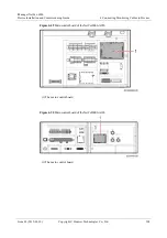
Страница 82: ...logies Co Ltd 71 Procedure Step 1 Connect one end of the network cable to the monitoring port on the smart cooling product For NetCol5000C 65kW 80kW open the rear door and connect one end of the network cable to the FE port on the main control panel of the smart cooling product Figure 4 15 NetCol5000C 65kW 80kW main control panel 1 Main control panel ...

Страница 83: ...r NetCol5000 A035 and NetCol5000 A020 open the front door and connect one end of the network cable to the FE port on the side of the smart cooling product LCD Figure 4 17 FE ports on the NetCol5000 A035 and NetCol5000 A020 For NetCol5000 A042 NetCol8000 C070 and NetCol8000 C150 open the rear door and connect one end of the network cable to the FE_1 port on the main control module of the smart cool...

Страница 84: ...ce Installation and Commissioning Guide 4 Connecting Monitoring Cables to Devices Issue 03 2019 03 10 Copyright Huawei Technologies Co Ltd 73 Figure 4 18 Position of the NetCol5000 A042 main control module 1 Main control module ...

Страница 85: ...s Issue 03 2019 03 10 Copyright Huawei Technologies Co Ltd 74 Figure 4 19 Positions of the NetCol8000 C070 and NetCol8000 C150 main control modules 1 Main control module Figure 4 20 Main Control Module 1 FE_1 port Step 2 Connect the other end of the network cable to the Ethernet port on the LAN switch End ...

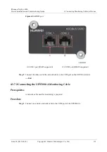
Страница 86: ... network cable used for monitoring is prepared Procedure Step 1 Connect one end of a network cable to the Ethernet port on the SNMP card of the UPS2000 G Figure 4 21 Ethernet port 1 Ethernet port Step 2 Connect the other end of the network cable to the Ethernet port on the switch End 4 2 5 2 Connecting the UPS5000G A Monitoring Cable Prerequisites A network cable used for monitoring is prepared Pr...

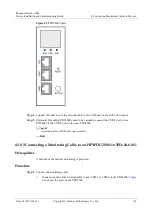
Страница 87: ...nstallation and Commissioning Guide 4 Connecting Monitoring Cables to Devices Issue 03 2019 03 10 Copyright Huawei Technologies Co Ltd 76 Figure 4 22 UPS5000 A 30 kVA 40 kVA functional components and control signal ports 1 FE port ...

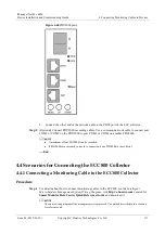
Страница 88: ...right Huawei Technologies Co Ltd 77 Figure 4 23 UPS5000 A 60 kVA 80 kVA 120 kVA functional components and control signal ports 1 FE port Figure 4 24 FE port on the UPS monitoring module of the 300 kVA UPS and models with higher capacities 1 FE port Step 2 Connect the other end of the network cable to the Ethernet port on the switch ...

Страница 89: ...dule Step 2 Connect the other end of the network cable to the Ethernet port on the LAN switch End 4 2 6 Connecting the PDU8000 Monitoring Cable Prerequisites A network cable used for monitoring is prepared Procedure Step 1 Connect one end of the network cable to the FE port in the display panel of PDU8000 as shown in Figure 4 25 Figure 4 25 Connecting the PDU8000 monitoring cable FE port 1 FE port...

Страница 90: ...isites A network cable used for monitoring is prepared Procedure Step 1 Connect one end of the network cable to the PoE port on the CIM Step 2 Connect the other end of the network cable to the Ethernet port on the switch End 4 3 Scenarios for Connecting the ECC500 Collector 4 3 1 Preparing a Monitoring Cable Prerequisites A twisted pair cord end terminal and RJ45 connector are prepared The followi...

Страница 91: ...ring the RS485 Monitoring Cable Figure 4 27 shows how to prepare a cord end terminal Figure 4 27 Preparing the RS485 monitoring cable for ECC collector Preparing a Dry Contact Monitoring Cable The method of preparing a dry contact monitoring cable is similar to the method of preparing the RS485 monitoring cable Prepare cord end terminals on both ends of each required core wire based on the number ...

Страница 92: ...with two wire and four wire cables and connect to the southbound intelligent equipment Independent Deployment AI DI Unit and intelligent ambient temperature and humidity sensor Figure 4 29 shows ports on the front panel of the RS485 communication card Figure 4 29 Front panel of the RS485 communication card 1 COM1 port 2 COM2 port 3 COM3 port 4 COM4 12V port 5 COM5 12V port 6 Indicators Table 4 6 d...

Страница 93: ...d on and 0 125 second off The RS485 communication card fails to communicate with the main control module ALM Red Alarm indicator Off No alarm is generated Steady on A board alarm is generated COM4 12V Green Port power output indicator Steady on The port properly provides the 12 V DC output COM5 12V Off The port provides no 12 V DC output Table 4 7 describes ports on the front panel of the RS485 co...

Страница 94: ...D COM4 12V and COM5 12V ports Pins 3 and 8 of these two ports provide 12 V DC power Therefore before connecting equipment to the ports check the equipment pin description to ensure that pins of the equipment match those on the ports preventing damage to ports or the equipment If an RS232 port transfers to an RS485 port and connects to an RS485 communications card one COM port connects to only one ...

Страница 95: ...our AI DI input ports to connect monitoring sensors and provide the DO control function Figure 4 31 shows ports on the front panel of the AI DI expansion card Figure 4 31 Front panel of the AI DI expansion card 1 DO control 2 AI DI_1 3 AI DI_2 4 AI DI_3 5 AI DI_4 6 Indicators Table 4 8 describes indicators on the front panel of the AI DI expansion card Table 4 8 Description of indicators on the fr...

Страница 96: ... communicating with the main control module properly Blinking 0 125 second on and 0 125 second off The AI DI expansion card fails to communicate with the main control module ALM Red Alarm indicator Off No alarm is generated Steady on A board alarm is generated Table 4 9 describes ports on the front panel of the AI DI expansion card Table 4 9 Description of ports on the front panel of the AI DI exp...

Страница 97: ...ately controlled Each port provides a maximum of 14 6 V 54 mAoutput power 4 3 3 Connecting a Monitoring Cable to an Independent Deployment AI DI Unit Prerequisites A network cable used for monitoring is prepared Procedure Step 1 Connect one end of the network cable to the COM_IN port on the independent deployment AI DI unit Step 2 Connect the other end of the network cable to the COM port with 12 ...

Страница 98: ...e is prepared Procedure Step 1 Connect one end of a common network cable to the hydrogen sensor RJ45 RS485 port Step 2 Connect the other end to the COM port on an ECC collector End 4 3 4 3 Connecting a Monitoring Cable to the SDLH 94R Dry Contact Type Smoke Sensor Prerequisites A monitoring cable required is prepared Context When connecting the SDLH 94R dry contact type smoke sensor and the ECC500...

Страница 99: ...or End 4 3 4 4 Connecting a Monitoring Cable to the Infrared Sensor Prerequisites A monitoring cable required is prepared Context When connecting the infrared sensor and the ECC500 collector you need to perform the following steps to prepare a special monitoring cable Procedure Step 1 Prepare an RJ45 connector on one end of the network cable by following to the instruction in 4 3 1 Preparing a Mon...

Страница 100: ...to the COM4 12V or COM5 12V port on the ECC500 collector A maximum of eight T H sensors can connect to each port End 4 3 4 6 Connecting Cables to the Region type Water Sensor Prerequisites A monitoring cable is prepared Procedure Step 1 Connect one end of the network cable to the Ethernet port on the water detector Step 2 Connect the other end of the network cable to the AI DI port on the ECC500 c...

Страница 101: ...rminal on the left of the access controller in the following figure and connect the double door and single door magnetic locks to the CH1 or CH2 terminal on the right of the access controller in the following figure The following figure uses the double door access controller as an example to illustrate the wiring method for the access control system In this example the fingerprint and card reader ...

Страница 102: ...print and Card Reader with a Keypad The following figure shows the cable connections to the access controller and fingerprint and card reader with a keypad using the cord end terminal to crimp the cable Figure 4 34 Connecting cables to the fingerprint and card reader with a keypad Connect one end of the network cable to the female connector of the fingerprint and card reader with a keypad Strip th...

Страница 103: ...and card reader with a keypad and connect the other end of the network cable to the non energized COM port on the ECC500 collector The following table shows the pin mapping for the RS485 port and the COM port Table 4 13 Pin mapping for the RS485 port and the COM port RS485 Port on Fingerprint and Card Reader with a Keypad COM Port on ECC500 Collector Pins Definition Pins Pin1 485A brown Pin1 Pin2 ...

Страница 104: ...minal at the terminal of the access controller Figure 4 36 shows the cable connections to the electromagnetic single swing door lock and an emergency door release button using the cord end terminal to crimp the cable The electromagnetic lock is delivered with a small white terminal Cut off the white terminal and then use a cord end terminal for crimping The cable installation sequences shown in th...

Страница 105: ... to the Double Door Interlock The double door interlock applies only to the four door access controller Magnetic lock 1 is installed on door 1 and magnetic lock 2 is installed on door 2 Card readers 1 and 2 are bound to the inside and outside of door 1 Card readers 3 and 4 are bound to the inside and outside of door 2 The CH2 and CH4 terminals on the right can be connected to the door status senso...

Страница 106: ...lled inside the access controller The access controller can obtain power from a power supply outside the equipment room Strip the cable install the connector BOM number 14170096 and connect the wires respectively to the L N and PE wiring terminals on the terminal block in the access controller power module as shown by 1 in Figure 4 39 Route the other end of the cable along the cable trough inside ...

Страница 107: ...ble 4 14 Power cable connection for the access controller Power Supply Cable Connection Power supply outside the equipment room Install the connector BOM number 14170096 to the other end of the power cable and connect the power cable to a circuit breaker in the power supply outside the equipment room Related Information Table 4 15 Card reader and key terminal definition Terminal Identity Definitio...

Страница 108: ...ck output power Passive output NP Passive output LKS Lock signal input ST Door magnetic signal input Gnd Common ground Table 4 17 Alarm input terminal definition Terminal Identity Definition AL 1 2 Two door controller no power supply output signal AL 1 4 Four door controller no power supply output signal Gnd Common ground Table 4 18 Power terminal definition Terminal Identity Definition LK P 12V L...

Страница 109: ...llow Green 10A Outdoor Cable CCC CE Access controller power cable 25030641 Electric Cable 300V UL2464 4x20AWG Black 4Cores Yellow Green Violet White 9A Non shielding Outdoor Cable UL Cable from the magnetic lock to the access controller 25030393 Electric Cable 300V 500V 60227 IEC 53 RVV 2x0 75mm2 Black 2Cores Brown Blue 6A Flat Outdoor Cable CCC CE Cable from the emergency door release button to t...

Страница 110: ...g Parameters for the Shengjiu_MS899 Electronic Door Lock Prerequisites A network cable used for monitoring is prepared Procedure Step 1 Connect the RJ45 end of the electronic lock cable to the COM port with 12 V power supply on the ECC500 collector End 4 3 5 3 Connecting a Monitoring Cable to the Door Status Sensor Prerequisites A monitoring cable required is prepared Context When connecting the d...

Страница 111: ...t from the door status sensor Step 4 Connect one end of the RJ45 network cable to the AI DI port on the ECC collector End 4 3 6 Connecting the Smart Cooling Product Monitoring Cable 4 3 6 1 Connecting the NetCol5000 Monitoring Cable Prerequisites A network cable used for monitoring is prepared Context When NetCol5000C 65kW 80kW NetCol5000 A042 A035 A025 A020 C030 connect to the NetEco over Modbus ...

Страница 112: ... Device Installation and Commissioning Guide 4 Connecting Monitoring Cables to Devices Issue 03 2019 03 10 Copyright Huawei Technologies Co Ltd 101 Figure 4 41 NetCol5000C 65kW 80kW main control panel 1 Main control panel ...

Страница 113: ...d connect the COM1 port on the first smart cooling product to the COM port on the ECC collector connect the COM2 port on the first smart cooling product to the COM1 port on the second smart cooling product and connect the other smart cooling products in the same way Amaximum of four smart cooling products can be networked Both the COM ports of NetCol5000 A042 and NetCol5000 A025 are on the main co...

Страница 114: ...Ltd 103 Figure 4 42 NetCol5000 A042 main control module 1 Main control module The position of the main control module in NetCol5000 A025 is the same as that in NetCol5000 A042 Figure 4 43 COM port on the main control module 1 COM port Open the smart cooling product rear door remove the filter and connect the network cable to the COM port on the NetCol5000 A035 ...

Страница 115: ...igure 4 44 NetCol5000 A035 COM port Open the smart cooling product rear door remove the filter and connect the network cable to the communications port J73 on the main control module in NetCol5000 A020 NetCol5000 C030 The following figure shows the pin sequence of the network cable that connects to the J73 communications port Figure 4 45 Pin sequence of a network cable ...

Страница 116: ...and Commissioning Guide 4 Connecting Monitoring Cables to Devices Issue 03 2019 03 10 Copyright Huawei Technologies Co Ltd 105 Figure 4 46 NetCol5000 A020 NetCol5000 C030 communications port J73 1 J73 teamwork bus port and host monitoring port ...

Страница 117: ... the M4 main control board The Arm7 main control board uses the software of V100R001 and the M4 main control board uses the software of V100R002 You need to set only the seventh toggle switch based on teamwork requirements and leave other toggle switches in their default status Figure 4 47 NetCol5000 main control board 1 Teamwork communication 1 2 Teamwork communication 2 3 S1 DIP switch of the ma...

Страница 118: ... cooling products to OFF 8 ON Remaining in ON Step 2 Connect the other end of the network cable to the COM port on the ECC collector End 4 3 6 2 Connecting the NetCol8000 Monitoring Cable Prerequisites A network cable used for monitoring is prepared Context When NetCol8000 A050 NetCol8000 A100 NetCol8000 C070 NetCol8000 C150 connect to the NetEco over MODBUS RTU connect cables by referring to this...

Страница 119: ...de 4 Connecting Monitoring Cables to Devices Issue 03 2019 03 10 Copyright Huawei Technologies Co Ltd 108 Figure 4 49 Main control board of the NetCol8000 A050 1 The main control board Figure 4 50 Main control board of the NetCol8000 A100 1 The main control board ...

Страница 120: ... 10 Copyright Huawei Technologies Co Ltd 109 Figure 4 51 Main control board of the NetCol8000 C070 1 The main control board Figure 4 52 Main control board of the NetCol8000 C150 1 The main control board Step 2 Connect one end of a network cable to the teamwork communications port 1 or 2 on the NetCol8000 main control board ...

Страница 121: ... the M4 main control board The Arm7 main control board uses the software of V100R001 and the M4 main control board uses the software of V100R002 You need to set only the seventh toggle switch based on teamwork requirements and leave other toggle switches in their default status Figure 4 53 NetCol8000 main control board 1 Teamwork communication 1 2 Teamwork communication 2 3 S1 DIP switch of the ma...

Страница 122: ...and last smart cooling products to ON and toggle switch 7 on the main control boards of the other smart cooling products to OFF 8 ON Remaining in ON Step 3 Connect the other end of the network cable to the COM port on the ECC collector End 4 3 7 Connecting the UPS Monitoring Cable 4 3 7 1 Connecting the UPS2000 G Monitoring Cable MODBUS Prerequisites A network cable used for monitoring is prepared...

Страница 123: ...Figure 4 54 RS485 port 1 COM1 port RS485 supported 2 COM2 port RS485 supported Step 2 Connect the other end of the network cable to the COM port on the ECC500 collector End 4 3 7 2 Connecting the UPS5000 A Monitoring Cable Prerequisites A network cable used for monitoring is prepared Procedure Step 1 Connect one end of a network cable to the COM port of the UPS5000 A ...

Страница 124: ...stallation and Commissioning Guide 4 Connecting Monitoring Cables to Devices Issue 03 2019 03 10 Copyright Huawei Technologies Co Ltd 113 Figure 4 55 UPS5000 A 30 kVA 40 kVA functional components and control signal ports 1 COM port ...

Страница 125: ...pyright Huawei Technologies Co Ltd 114 Figure 4 56 UPS5000 A 60 kVA 80 kVA 120 kVA functional components and control signal ports 1 COM port Figure 4 57 port on the UPS monitoring module of the 300 kVA UPS and models with higher capacities 1 COM port Step 2 Connect one end of the network cable to the COM port on the ECC collector ...

Страница 126: ...pared Procedure Step 1 Connect one end of the network cable to the COM port in the display panel of PDU8000 Figure 4 58 Connecting the PDU8000 monitoring cable COM port 1 COM port Step 2 Connect the other end of the network cable to the COM port of the ECC collector End 4 3 8 2 Connecting a Monitoring Cable to the Monitoring Type PDU2000 32 1PH 20 4 M1 Prerequisites A network cable used for monito...

Страница 127: ...ector Step 3 Optional If multiple PDU2000s need to be cascaded connect the COM1 port of one PDU2000 to the COM2 port on the next PDU2000 A maximum of four PDU2000s can be cascaded End 4 3 8 3 Connecting a Monitoring Cable to an HPXPDU2000 16 3PH 24 6 M1 Prerequisites A network cable used for monitoring is prepared Procedure Step 1 Connect the monitoring cable 1 Connect one end of the network cable...

Страница 128: ...n another PDU2000 A maximum of four PDU2000s can be cascaded If PDU2000s are cascaded you need to connect only one PDU2000 to the collector End 4 4 Scenarios for Connecting the ECC800 Collector 4 4 1 Connecting a Monitoring Cable to the ECC800 Collector Procedure Step 1 For details about how to connect monitoring cables to the ECC800 see the Intelligent Micro Module Management System Wiring Diagra...

Страница 129: ...iManager NetEco 6000 Device Installation and Commissioning Guide 4 Connecting Monitoring Cables to Devices Issue 03 2019 03 10 Copyright Huawei Technologies Co Ltd 118 End ...

Страница 130: ...r than 5 MΩ 4 All the screws are secure a flat washer and a spring washer are installed for each screw the washers are properly placed 5 The cabinets are arranged in order The cabinet queue at both sides of the passage are straight and the difference does not exceed 5 mm 6 The connecting plates are installed properly when two cabinets are deployed on one site 7 The front side and rear doors of the...

Страница 131: ...or lever of each board is placed in position 7 The captive screws of each board are secure 8 There is no vacant slot in the subrack and filler panels are installed in vacant slots 9 A protective cover is installed for the power module if the power module is configured with a protective cover 5 3 Checking the Installation of Power Cables and Ground Cables SN Check Item 1 All the power cables and gr...

Страница 132: ...e connectors 4 Proper length is reserved for signal cables at turning points The turning radius meets the requirement 5 The optical fibers must be sheathed using corrugated pipes at outsides of cabinets Both ends of the pipes must be fastened The edges are smooth or be processed for cutting prevention 6 No other cables are laid on optical fibers 7 The extra optical cables are coiled on the cable c...

Страница 133: ...ble server scenarios see the iManager NetEco 6000 High Availability System Product Documentation Table 6 1 Encryption algorithms Insecure Encryption Algorithm Secure Encryption Algorithm DES 3DES excluding the scenario in which K1 K2 K3 is used SKIPJACK RC2 RSA 1024 bits or less MD2 MD4 MD5 needs to be used in the scenarios where digital signatures are generated or passwords are encrypted before s...

Страница 134: ...the NetEco client by web browser You have the operation rights for Data Center Planning Context The types of the managed domain Park Building Room Container Subnet NetecoSite You are advised to plan the affiliation before configuring the managed domains To create management domain note that You can create Park Building Building ShapeNode ContainerDC Room Room ShapeNode Subnet NetecoSite FusionModu...

Страница 135: ...der 3 In the right side of the view area set Management Info You can configure Management Info Electricity Info and Refrigeration Info for the equipment room management domain Table 6 3 lists the configuration parameters for Park Building ContainerDC and Subnet Table 6 3 and Table 6 4 list the configuration parameters for Room and NetecoSite Table 6 3 Management domain parameter list 1 Item Descri...

Страница 136: ...gured for two or more management domains you can query the management domain information on the map on the Asset Overview page Range 180 to 180 Latitude Latitude of the position where the created management domain is located NOTE After this parameter is configured You can view the GIS map corresponding to the management domain on the Data Center View page When this parameter is configured for two ...

Страница 137: ...t exceed the planned number of rack places Range integer from 1 to 2000 Wire Laying Cabling mode of the created management domain Select Upline or Downline from the drop down list box Address Location of the created management domain Range 0 128 characters City Name of the city where the created management domain is located Range 0 128 characters Country Name of the country where the created manag...

Страница 138: ...Vertical under floor Air distribution or Horizontal displacement Air distribution from the drop down list box Plan Refrigeratin g Capacity k W Cooling power of the created management domain Range floating point number of 1 10000000 accurate to three decimal places The parameters with must be set Other parameters are optional The value of Planned Rack Position cannot be changed after it is set The ...

Страница 139: ... the left Step 3 Click Domain The infrastructure area is displayed Step 4 Select Modular from the Type drop down list as shown in Figure 6 1 Figure 6 1 Selecting the modular Step 5 Select the Modular to be added and drag the modular icon to the Room area as shown in Figure 6 2 Figure 6 2 Adding the modular in the room area Step 6 Modify Management Info of the module based on Table 6 5 or retain th...

Страница 140: ...onal list Parent Object Management domain of the device The NetEco automatically identifies this name Type Device type The NetEco automatically identifies this name Manufact urer Manufacturer of the device The value contains 1 to 64 characters Serial Number Device number The value contains 0 to 64 characters Location Location of the device The value contains 0 to 64 characters Install Mode Set to ...

Страница 141: ...can delete one modular or multiple modulars in batches on the current page If a modular contains sub devices you cannot delete the modular You can delete the modular only after you delete sub devices in the modular Delete one module a Select Modular and click Delete under as shown in Figure 6 3 Figure 6 3 Deleting one module page b In the displayed Confirm dialog box click Yes Delete multiple modu...

Страница 142: ...Eco client by web browser An SMS modem has been installed and commissioned You have obtained the interworking parameters such as the phone number for receiving the notification of the SMS modem from users You have the operation rights for Set Notified Server Context The SMS modem is not supported in cloud deployment scenarios You need to input calling number and Email for sending remote alarm noti...

Страница 143: ...cting the SMS modem on the server COM1 or COM2 SMS modem bound rate SMS modem bound rate provided in the SMS modem user manual 115200 9600 or 4800 Mobile number for receiving notification Phone number to which the short messages are sent NOTE Mobile number for receiving notification must be set according to the following requirements 1 A country code must be added preceding the calling number For ...

Страница 144: ... The default settings of the IP address subnet mask and gateway are as follows IP address 192 168 0 10 Subnet mask 255 255 255 0 Gateway 192 168 0 1 Context The parallel CIM communication is used to synchronize the analog parameters and configuration parameters of each CIM system It can also be used to coordinate the measurement of internal resistance so that only one BIM is measuring the internal...

Страница 145: ...the access security change the password after the first login If you enter wrong passwords for five consecutive times the system will be locked for one hour After that you can operate normally If you forget the IP address hold down the Default button on the CIM for more than 10 seconds Then the ALM indicator blinks at short intervals and the CIM IP address is restored to the factory default value ...

Страница 146: ... 5 Set CIM parallel parameters If multiple CIMs need to be connected to a LAN switch set Parallel The following parameter settings use the parallel CIMs as an example For operation on a single CIM refer to this section 1 On the CIM WebUI home page choose Monitoring CIM System Running Parameter Parallel Configuration and select Parallel Figure 6 9 Setting parameters for the parallel system ...

Страница 147: ...iguring the communication address for the parallel CIMs 4 On the CIM WebUI home page choose Monitoring CIM System Running Parameter Basic Information and set Current source Battery N wire Total battery capacity Batt installation time and Multi Hall cur setting The value of Multi Hall cur setting equals the number of positive or negative Hall effect sensors in a single battery string and should be ...

Страница 148: ...d in to the NetEco client You have the operation rights for Data Center Planning You have created a management domain for the device to be added on the Data Center Planning page Context You can create a CIM01C2 collector by manually creating the CIM01C2 on the NetEco or by adding a UPS for synchronizing the CIM01C2 to the NetEco UPSs of the following types allow you to synchronize a CIM01C2 to the...

Страница 149: ...click the Device tab Step 4 Click the drop down list box in Type and select Battery Detector Step 5 Select the device to be added and drag its icon to the management domain To delete a device click the device and choose Delete under Step 6 Specify parameters based on Table 6 7 The CIM01C2 complying with the MODBUS TCP protocol is used as an example The following table lists the parameters Figure 6...

Страница 150: ... device at the same time NOTE Connection Mode for the NetEco and device must be the same By default Connection Mode is set to SSL Connection for the NetEco and device NOTE Battery detectors accessed through the UPS do not support device software management Authentication Password Indicates the re authentication password for the NetEco and device 1 Click Modify 2 In the displayed dialog box enter t...

Страница 151: ...ed hold down the BIM networking switch for at least 5 seconds to clear the original network Context To prevent the BIM in a group connects to another CIM ensure that only one CIM is under networking at a time That is only the RF_Z indicator on this CIM is blinking at super short intervals Procedure Step 1 Press the networking switch on the CIM for 2 seconds The ALM indicator blinks red once and th...

Страница 152: ...tep 5 Optional If multiple CIMs are cascaded repeat Step 1 to Step 4 to perform networking for remaining CIMs and BIMs End Follow up Procedure If the UPS does not charge batteries for a long time power off the CIMs to prevent damage to batteries After the CIMs have been powered off for 30 minutes the BIMs will hibernate automatically if the voltage of 2 V batteries is less than 2 1 V or the voltag...

Страница 153: ...IP address according to the site requirements Figure 6 16 Configuring the server Set Business IP to XXX XXX XXX XXX Subnet mask to XXX XXX XXX XXX Gateway IP to XXX XXX XXX XXX The values here are examples The actual values prevail Set NAT IP to VCN500 external IP address 4 Configure the NTP synchronization After setting The NTP clock source server to Yes set the IP address of the NTP server The s...

Страница 154: ...VCN500 IP address enter the VCN500 IP address in the address box of the Internet browser and log in to the OMU Portal system Optional Deploying IVS in Stack Mode For details for details refer to Optional Deploying IVS in Stack Mode in VCN500 Product Documentation Log in to http e huawei com to obtain the document Optional Deploying MPUs in Cluster Mode for details refer to Optional Deploying MPUs ...

Страница 155: ...browser for logging in to the camera through the WebUI Windows 7 Internet Explorer 8 9 10 11 Chrome 32 and FireFox 35 51 Windows 8 Internet Explorer 10 11 Chrome 32 and FireFox 35 51 Windows 10 Internet Explorer 11 Chrome 32 and FireFox 35 51 Google Chrome 45 or later versions need to install the Internet Explorer tab plug in Only 32 bit web browsers are supported 2 Enter the preset user name admi...

Страница 156: ... NetEco 6000 Device Installation and Commissioning Guide 6 Adding Devices Issue 03 2019 03 10 Copyright Huawei Technologies Co Ltd 145 Set coding protocol to H 265 Figure 6 20 Setting primary stream parameters ...

Страница 157: ...cameras After commissioning the connected camera commission other cameras in the same way Procedure Step 1 Log in to the camera WebUI 1 Configure the PC IP address and the camera IP address in the same network segment Enter the camera IP address 192 168 0 120 by default in the address bar of the Internet Explorer and press Enter button The following lists the requirements of the operating system a...

Страница 158: ...and the preset password HuaWei123 and click Log In Step 2 Preview the site situation in real time and check the camera coverage through videos Adjust the lens if necessary Step 3 Choose Settings Setting Network Parameters Setting Basic Network Parameters and set IP address Subnet mask and Gateway IP address for the camera according to the site plan Step 4 Set camera stream type primary stream and ...

Страница 159: ...he camera is normal The version number is subject to the Quick Start delivered with the VCN500 The description and link in this document are for reference only Procedure Step 1 Install Client Server C S client 1 Download the client server C S client You can obtain the C S client in either of the following ways Method 1 Obtain the HW_IVS_Client exe file from the software CD ROM delivered with the V...

Страница 160: ...Quick Setup area on the C S client home page double click Add Camera 2 Set the searching criteria for cameras and click Next after setting 3 Search for and verify the camera Then select the camera and click Next 4 Preview live video images click the camera in the camera list on the left and adjust camera parameters to optimize the image effect Then click Next 5 Optional Group the cameras and click...

Страница 161: ...ber of the server NOTE The default port number for VCN500 is 9900 9900 Server Version Indicates the version of the server VCN500 Login User Indicates the user name for logging in to the IVS client NOTE Only browsing and query permissions are required on the NetEco Configure video system users who have only browsing and query permissions The default user name for VCN500 is Admin It is recommended t...

Страница 162: ...et the transmission protocol in the same way as setting the protocol using eSpace IVS The path for setting the transmission protocol is as follows Para Setting Local Parameter Transmission protocol The transmission protocol can be UDP or TCP TCP Step 4 Click Test after configuring parameters During the first test the page turns blank Wait 30s If the test fails a message indicating a connection fai...

Страница 163: ...ces Issue 03 2019 03 10 Copyright Huawei Technologies Co Ltd 152 Figure 6 24 Security tab page Step 3 Add the IP address of the client to the trusted site list 1 Select Trusted sites and click Sites Add the IP address of the client to the trusted site list as shown in Figure 6 25 ...

Страница 164: ...Click Add and then click Close Step 4 Enable ActiveX related options for trusted sites After ActiveX related options are enabled a message is displayed indicating that the computer is prone to risks due to security settings Ignore the message 1 Choose Trusted sites From definition rank The Security setting trusted stand region dialog box is displayed as shown in Figure 6 26 ...

Страница 165: ...he determination need to change the establishment of this region Click Yes Step 5 Register with the OCX plug in Restart Internet Explorer and enter the IP address to be accessed by the client The page for watching videos is displayed Click Install according to the prompt message After the OCX plug in is installed you can watch the videos If videos are not displayed contact Huawei technical support...

Страница 166: ... not in any management domain to a management domain using the automatic discovery function provided by the system Prerequisites You have logged in to the NetEco client by web browser You have the operation rights for Camera Management You have set parameters on the Parameter Configuration page and the connection between the NetEco and VCN500 server is successful A camera has connected to the VCN5...

Страница 167: ...nt domain on the Data Center Planning page On the Data Center Planning page you can set parameters such as the Name for the camera End Follow up Procedure Table 6 9 describes the operations that can be performed on the Discovery Camera page Table 6 9 Follow up procedure If You Want To Then Query the information about a camera 1 On the Discovery Camera page specify one or multiple of the keywords C...

Страница 168: ...042 C025 C030 smart cooling products support MODBUS TCP MODBUS RTU and SNMP protocols When NetCol5000C 65kW 80kW NetCol5000 A042 C025 C030 smart cooling products use MODBUS TCP connection refer to this section for configuration details This section uses NetCol5000 A035_V100R002C00 as an example Procedure Step 1 Tap Settings on the NetCol5000 A035_V100R002C00 home screen Step 2 Enter the administra...

Страница 169: ...ble The default value is Enable This parameter is configurable when Connection mode is set to Client Server encryption Enable Disable The default value is Disable This parameter is configurable when Connection mode is set to Server EMS IP address Enter the actual IP address of the EMS IP addresses of the display panel client EMS and server EMS must be unique This parameter is configurable when Con...

Страница 170: ...gement domain for the device to be added on the Data Center Planning page Procedure Step 1 Choose Configuration Configuration Management Data Center Planning from the main menu The Data Center Planning window is displayed Step 2 Select the management domain to add a device Step 3 In the lower left corner of the page click the Device tab Step 4 Click the drop down list box in Type and select Air Co...

Страница 171: ...ing Devices Issue 03 2019 03 10 Copyright Huawei Technologies Co Ltd 160 Figure 6 28 Configuring parameters for the NetCol5000 MODBUS TCP Table 6 12 MODBUS TCP device parameter description Parameter Description Name Device name IP address Set the IP address of the device ...

Страница 172: ...must modify Connection Mode on the WebUI of the device at the same time NOTE Connection Mode for the NetEco and device must be the same By default Connection Mode is set to SSL Connection for the NetEco and device Authentication Password Indicates the re authentication password for the NetEco and device 1 Click Modify 2 In the displayed dialog box enter the New Password and Confirm Password NOTE T...

Страница 173: ...address on the UPS2000 G 1 Press next to UPS2000 G screen 2 Press select Settings 3 Press input password The preset password is 000001 To protect the access security change the password after logging in to the coulometer for the first time 4 Press select Communication card 5 Press to enter the IP address setting 6 Press set the value size by and 7 Press and move the cursor to Sub mask and Default ...

Страница 174: ...n in Figure 6 30 Figure 6 30 Setting SNMP parameters_02 6 Input the User Name MD5 password and DES password set Permission to Write and click Add Record the User Name MD5 password and DES password for using when creating a UPS2000 G on the NetEco You are advised to set MD5 Password and DES Password to different values Figure 6 31 Setting SNMP parameters_03 7 Click Add in SNMP Trap and Permission S...

Страница 175: ... UPS5000 Monitoring Parameters over SNMP Prerequisites You have obtained the IP address subnet mask and default gateway planned for the UPS5000 The UPS5000 is powered on Context Before connecting the UPS5000 to the NetEco set the IP address on the UPS5000 and add a user and set rights on the UPS5000 WebUI UPS WebUIs may vary slightly depending on the UPS software version Perform operations based o...

Страница 176: ...dress box of a browser and press Enter The UPS5000 IP address is set in step 1 2 Enter the User name and Password of the UPS5000 and click Login The preset user name and password are admin and Changeme respectively for the UPS5000 3 Choose Config Site Config 4 In the SNMP area set SNMP version to SNMPv3 and set SNMP port to 161 Figure 6 34 Setting SNMP parameters 5 Click Add in SNMP Figure 6 35 Se...

Страница 177: ...ations addresses are unique 1 Log in to the UPS5000 WebUI 2 Choose Monitoring Comm Config RS485 Settings and verify that Address is set to 1 for the UPS5000 3 Choose Monitoring CIM Param Basic Param and verify that CIM logical start addr is set to 2 for the UPS5000 End 6 3 4 3 Setting UPS5000 Monitoring Parameters over Modbus TCP Prerequisites You have obtained the IP address subnet mask and defau...

Страница 178: ...d Changeme respectively for the UPS5000 3 Set UPS5000 parameters Table 6 13 UPS5000 settings Connection Mode NetEco UI Operation UPS5000 WebUI SSL connection 1 Set ModbusTCP encryption to Enable and click Submit Path Monitoring Param Settings Advanced Param 2 Set Authenticaiton to Enable set New password and Confirm password and click Submit Record the value of Confirm password which need to be fi...

Страница 179: ...se Configuration Configuration Management Data Center Planning from the main menu The Data Center Planning window is displayed Step 2 Select the management domain to add a device Step 3 In the lower left corner of the page click the Device tab Step 4 Click the drop down list box in Type and select UPS Step 5 Select the device to be added and drag its icon to the management domain To delete a devic...

Страница 180: ... Configuring parameters for a UPS5000 MODBUS TCP Table 6 14 MODBUS TCP device parameter description Parameter Description Name Device name IP Address Set the IP address of the device Port Set this parameter to the port through which the device connects to the collector The port number is 502 by default You can modify the port number based on requirements ...

Страница 181: ...ed 2 In the displayed dialog box enter the New Password and Confirm Password NOTE The default re authentication password for the NetEco and device is Modifyme_123 The device password should be consistent with the NetEco password If the password does not meet requirements modify it on the device 3 Choose Send To Device NOTE If you click YES the re authentication password for the NetEco and device i...

Страница 182: ...col set on the device The default selection is SHA Support SHA and MD5 agreement Authentication Password Set this parameter to the SHA or MD5 password set on the device Privacy Protocol Set this parameter to the privacy protocol set on the device The default selection is AES Support CBC_DES AES128 AES192 and AES256 agreement Privacy Password Set this parameter to the AES or DES password set on the...

Страница 183: ...e PDU8000 are respectively admin and 000001 To ensure access security change the password upon first login Step 3 Tap Communication 1 Check that IP address assign is set to Manual 2 Set IP address Subnet mask and Gateway as planned 3 Click SNMP Configuration and enter to the screen Figure 6 38 SNMP Configuration 4 In SNMP Config page set SNMP Version to SNMPv3 retain SNMP Port default value 161 an...

Страница 184: ...1 Choose Configuration Configuration Management Data Center Planning from the main menu The Data Center Planning window is displayed Step 2 Select the management domain to add a device Step 3 In the lower left corner of the page click the Device tab Step 4 Click the drop down list box in Type and select PDU Step 5 Select the device to be added and drag its icon to the management domain To delete a...

Страница 185: ...ight Huawei Technologies Co Ltd 174 Figure 6 39 Configuring parameters for a PDU SNMPv3 Table 6 17 SNMP v3 device parameter description Parameter Description Name Device name IP Address Set this parameter to the device IP address Port Set this parameter to the port number of the device set to 161 by default ...

Страница 186: ...Privacy Password Set this parameter to the AES or DES password set on the device NOTE You are advised to set Authentication Password and Privacy Password to different values Timeout period Timeout duration for connection test set to 3s by default Step 7 Click Connection Test to start the connection test Step 8 After the connection test is successful click in the toolbar to save the device informat...

Страница 187: ...ta Center Planning window is displayed Step 2 Select the management domain to add a device Step 3 If the management domain is a rack DDF or power cabinet click the management domain and choose Design under The page for adding a device is displayed Otherwise skip this step Step 4 In the lower left corner of the page click the Device tab Step 5 Click the drop down list box in Type and select RPDU St...

Страница 188: ... Huawei Technologies Co Ltd 177 Figure 6 40 Configuring the power module SNMP v3 parameters Table 6 18 SNMP v3 device parameter description Parameter Description Name Device name IP Address Set this parameter to the device IP address Port Set this parameter to the port number of the device set to 161 by default ...

Страница 189: ...ord and Privacy Password to different values Timeout period Timeout duration for connection test set to 3s by default Step 8 Click Connection Test to start the connection test Step 9 After the connection test is successful click in the toolbar to save the device information End 6 3 7 Adding a RPDU 6 3 7 1 Setting RPDU_HUAWEI_PDU2000 32 1PH 20 4 M2 Monitoring Parameters Prerequisites You have obtai...

Страница 190: ...hts for Data Center Planning You have created a management domain for the device to be added on the Data Center Planning page Procedure Step 1 Choose Configuration Configuration Management Data Center Planning from the main menu The Data Center Planning window is displayed Step 2 Select the management domain to add a device Step 3 If the management domain is a rack or a DDF click the management do...

Страница 191: ...arameters Table 6 20 SNMP v1 v2 device parameter description Parameter Description Name Device name IP Address Set this parameter to the device IP address Port Set this parameter to the port number of the device set to 161 by default Read Community Set this parameter to the read community set on the device set to public by default Modifying community per three months is advised ...

Страница 192: ...r name added in SNMPv3 on the WebUI of the device Authentication Protocol Set this parameter to the authentication protocol set on the device The default selection is SHA Support SHA and MD5 agreement Authentication Password Set this parameter to the SHA or MD5 password set on the device Privacy Protocol Set this parameter to the privacy protocol set on the device The default selection is AES Supp...

Страница 193: ...k the Advancedtab and select Use TLS1 1 and Use TLS1 2 You have installed hardware for the ECC500 V6 collector and powered it on A PC with an IP address in the same network segment as the ECC500 V6 collector is prepared and the PC has been connected to the ECC500 V6 collector over a switch You have obtained the planned IP address subnet mask and default gateway for the ECC500 V6 collector Context ...

Страница 194: ...he ECC500 V6 collector If you log in to the ECC500 V6 collector for the first time enter admin as the user name and 000001 or Changeme as the password After you log in to the ECC500 V6 collector successfully change the password for security For details see 8 5 How to Change the Preset Password for the ECC500 Collector Step 4 Choose System Settings IP Address Settings set the IP address subnet mask...

Страница 195: ...e Click Submit and click OK in the displayed dialog box In Challenge certification password click Reset Password In the displayed dialog box click OK to restore the preset password 3N Se7q4152H5X Alternatively in Challenge certification password set New Password and Confirm password and then click Change password Keep in mind the password that is set in Challenge certification password The passwor...

Страница 196: ...the ECC500 V6 Collector You need to set the SNMP parameters for the ECC500 V6 collector if it connects to the EMS as these parameters are needed for setting up the ECC500 V6 collector on the EMS Prerequisites You have obtained the IP address login user name and password for the ECC500 V6 collector A PC with an IP address in the same network segment as the ECC500 V6 collector is prepared and the PC...

Страница 197: ...characters complying with the system can be entered for User Name MD5 SHA Password and DES AES Password Record the specified parameters as you will need them when setting up the ECC500 V6 collector on the NetEco MD5 SHAPassword and DES AES Password need to be set to different passwords MD5 and DES encryption algorithms are not secure It is recommended that you set protocol to SHA and AES The follo...

Страница 198: ...ap Target Address and Trap Port and select SNMP Version Set Trap Target Address to the NetEco server IP address and set Trap Port to the user defined port The default value of Trap Port is 162 Step 10 Select SNMPv3 for SNMP Version and a user name for SNMPv3 Step 11 After you set the parameters click Confirm Step 12 Click Submit as shown in Figure 6 49 Figure 6 49 Setting the SNMPv3 parameters 05 ...

Страница 199: ...he devices This topic describes how to set RS485 port parameters for the COM1 port on the MUS02A card of the ECC500 V6 collector Procedure Step 1 Set RS485 port parameters on the WebUI of the ECC500 V6 collector 1 Use a PC enter https XX XX XX XX in the address bar to log in to the WebUI of the ECC500 V6 collector XX XX XX XX indicates the IP address of the collector To ensure the security of data...

Страница 200: ... card can be inserted into any one or more slots among slots 1 4 on the ECC500 V6 collector The RS485 port numbers vary based on slots Figure 6 51 shows the ECC500 V6 collector slots Table 6 22 shows the mappings between slots and port numbers During onsite operations connect the slots on the collector based on site requirements The following figure is only for reference Figure 6 51 ECC500 V6 coll...

Страница 201: ... Data Center Planning from the main menu The Data Center Planning page is displayed Step 2 Select the management domain to add a device The management domain can be a rack power cabinet or DDF Step 3 Click the management domain and choose Design under the The page for adding a device is displayed Step 4 In the lower left corner of the page click the Device tab Step 5 Click the drop down list box i...

Страница 202: ...iguring parameters for the ECC500 V6 collector Table 6 23 SNMP v3 device parameter description Parameter Description Name Device name IP Address Set this parameter to the device IP address Port Set this parameter to the port number of the device set to 161 by default Security Name Set this parameter to the user name added in SNMPv3 on the WebUI of the device ...

Страница 203: ... Click Connection Test to start the connection test Step 9 After the connection test is successful click in the toolbar to save the device information End 6 4 2 Adding Sensors 6 4 2 1 Adding Dry Contact Interface Devices 6 4 2 1 1 Setting Door Status Sensor Monitoring Parameters on the ECC After connecting a door status sensor DSS to the AI DI port of an ECC500 V6 collector you need to set DSS par...

Страница 204: ...E05A4 Running Parameter AI DI_1 Port Settings Step 3 Select Enable for AI DI_1 Sensor Step 4 Click Submit as shown in Figure 6 53 Figure 6 53 Setting port enabling of a dry contact Step 5 Select Door Sensor for AI DI_1 Sensor Type from the drop down list as shown in Figure 6 54 Figure 6 54 Setting the sensor type of a dry contact Step 6 Set AI DI_1 Power Supply to On Step 7 Click Submit End ...

Страница 205: ...ontext This section describes how to set smoke sensor or water leakage sensor monitoring parameters when a smoke sensor or water leakage sensor is connected to the AI DI_1 port of the MUE05A4 card of an ECC500 V6 collector Set the parameters based on the actual port connected to the smoke sensor or water leakage sensor onsite A smoke sensor or water leakage sensor is a self identification device A...

Страница 206: ... device parameters of the NO or NC dry contact on the WebUI Prerequisites You have obtained the IP address and login user name and password for the ECC500 V6 collector A PC with an IP address in the same network segment as the ECC500 V6 collector is prepared and the PC has been connected to the ECC500 V6 collector over a switch Context An NO or NC dry contact is a device whose normal status signal...

Страница 207: ...DI_1 Sensor Step 4 Click Submit as shown in Figure 6 57 Figure 6 57 Setting port enabling of a dry contact Step 5 Select NO or NC for AI DI_1 Sensor Type from the drop down list as shown in Figure 6 58 Figure 6 58 Setting the sensor type of a dry contact NO indicates a normally open dry contact The dry contact will report an alarm in the normally closed state NC indicates a normally closed dry con...

Страница 208: ...ensor in an equipment room or container Prerequisites You have logged in to the NetEco client by web browser You have the operation rights for configuring Data Center View Procedure Step 1 Choose Monitor Topo Data Center View from the main menu The Data Center View window is displayed Step 2 In the 3D view editing window click The Toolbox dialog box is displayed Step 3 Drag to the required positio...

Страница 209: ...e Setting Rule dialog box is displayed 1 In the Setting Rule dialog box configure the real time value The value consistent with real time signal value 2 Click OK Figure 6 60 Setting Rule Step 5 In the Basic Properties pane in the Property Panel dialog box click following the Attributeto configure data for the door status sensor icon Step 6 On the displayed Select Data page select Managed Object an...

Страница 210: ...d choose Close or Open under 2 In the displayed dialog box click Yes Step 7 Click following the Current Alarm Select alarms to be bound to the icon Figure 6 61 Binding alarms Step 8 Click Yes You can bind a maximum of 20 alarms to a measurement object After an alarm is bound with a device icon the color of the device icon will be changed to that of the color indicating that the bound alarm is gene...

Страница 211: ...bind the managed objects indicators and alarms Prerequisites You have logged in to the NetEco client by web browser You have the operation rights for configuring Data Center View Procedure Step 1 Choose Monitor Topo Data Center View from the main menu The Data Center View window is displayed Step 2 In the 3D view editing area click on the toolbar The Toolbox dialog box is displayed Step 3 Drag to ...

Страница 212: ...sue 03 2019 03 10 Copyright Huawei Technologies Co Ltd 201 Figure 6 63 Property Panel Step 4 Click following the Attribute In the Select Data dialog box select managed objects and indicators Step 5 Click OK Step 6 Click following the Current Alarm Select alarms to be bound to the icon ...

Страница 213: ...e 6 64 Binding alarms Step 7 Click Yes You can bind a maximum of 20 alarms to a measurement object After an alarm is bound with a device icon the color of the device icon will be changed to that of the color indicating that the bound alarm is generated Step 8 In the Property Panel click Extend Properties then configure basic properties for the icon ...

Страница 214: ...MP_V1 2 Obtain the method for modifying alarm names for dry contacts on the NetEco according to the following table Table 6 24 References for different access packages ECC500 V6 Access Package Reference Section MED_Collector_HUAWEI_ECC500V6_S NMP_V1 1 Modifying Alarm Names for Dry Contacts on the NetEco for V1 1 MED_Collector_HUAWEI_ECC500V6_S NMP_V1 2 Modifying Alarm Names for Dry Contacts on the...

Страница 215: ...a Center Planning from the main menu The Data Center Planning window is displayed 2 In the navigation tree on the left select a collector in the rack to switch to the rack design page 3 In the parameters setting area of the collector expand the corresponding Extended Info tab as shown in the following figure The mapping relationship between the Extended Info tab name and the collector port is disp...

Страница 216: ...Extended information of the ECC500 V6 collector on the NetEco Table 6 25 Mapping between the Extended Info tab name and the collector port and independent deployment AI DI unit Extended Info Tab Name on the NetEco Measurement Object Slot Number of the RS485 Card Port Number of the RS485 Card Communicati ons Address of the independent deployment AI DI unit ...

Страница 217: ...MUE06A1 31 3 COM4 1 Extended Info MUE06A2 32 3 COM5 1 Extended Info MUE06A3 33 3 COM4 2 Extended Info MUE06A4 34 3 COM5 2 Extended Info MUE06A5 35 4 COM4 1 Extended Info MUE06A6 36 4 COM5 1 Extended Info MUE06A7 37 4 COM4 2 Extended Info MUE06A8 38 4 COM5 2 Table 6 26 Mapping between independent deployment AI DI unit communications address and DIP switch Communications Address of the independent d...

Страница 218: ...ied 5 Click to save the changes Modifying Alarm Names for Dry Contacts on the NetEco for V1 2 1 On the main menu choose Alarm Alarm Operation Alarm Settings to go to the Alarm Settings page 2 In the navigation pane on the left choose Custom Alarm Redefine Alarm 3 Click Create 4 Click Select Alarm In the displayed dialog box select Collector_HUAWEI_ECC500V6_SNMP for Device Type on the left select t...

Страница 219: ...AI DI unit of an ECC500 V6 collector you need to set temperature sensor monitoring parameters on the web user interface WebUI of the collector Prerequisites You have obtained the IP address and login user name and password for the ECC500 V6 collector A PC with an IP address in the same network segment as the ECC500 V6 collector is prepared and the PC has been connected to the ECC500 V6 collector o...

Страница 220: ... Copyright Huawei Technologies Co Ltd 209 Figure 6 68 Setting port enabling of an NTC sensor Step 4 Click Submit Step 5 Check whether AI DI_1 Sensor Type is automatically identified as NTC Figure 6 69 Setting the sensor type of an NTC sensor Step 6 Set AI DI_1 Power Supply to On Step 7 Click Submit End ...

Страница 221: ... AI DI unit of an ECC500 V6 collector to set the device IP address to 1 or 2 Figure 6 70 shows the DIP switch and Table 6 28 describes the setting method Figure 6 70 DIP switch of an independent deployment AI DI unit 1 DIP switch on an independent deployment AI DI unit of an ECC500 V6 collector The DIP bits are bit 1 bit 2 bit 3 and bit 4 from the left to the right Toggle switches 1 3 specify the ...

Страница 222: ...Center Planning page Procedure Step 1 Choose Configuration Configuration Management Data Center Planning from the main menu The Data Center Planning window is displayed Step 2 Select the management domain to add a device Step 3 If the management domain is a rack click the management domain and choose Design under The page for adding a device is displayed Otherwise skip this step Step 4 In the lowe...

Страница 223: ...Description Name Device name IP address Set this parameter to the IP address of the collector to which the device is connected Port The NTC port number is the same as the ECC port number for the independent deployment AI DI unit Fill in the actual value by referring to Setting RS485 Parameters for the ECC500 V6 Collector Device address The device address is configured using the DIP switch of the i...

Страница 224: ...1 and so on Step 8 Click Connection Test to start the connection test Step 9 After the connection test is successful click in the toolbar to save the device information End 6 4 2 2 4 Viewing a Temperature Map on the NetEco Prerequisites A temperature sensor has been successfully connected You have logged in to the NetEco client You have created a management domain for the device to be added on the...

Страница 225: ...sor is obtained The ambient temperature and humidity sensor connects to the collector and displays values on the display panel The IP address user name and password for logging in to the collector are obtained A PC with an IP address in the same network segment as the collector is prepared and the PC connects to the collector over a switch Context Before connecting the ambient temperature and humi...

Страница 226: ... StopBit and Parity of the device For ECC collector settings see 6 4 1 4 Setting RS485 Parameters for the ECC500 V6 Collector End 6 4 2 3 2 Creating a Temperature and Humidity Sensor on the NetEco Prerequisites You have logged in to the NetEco client You have the operation rights for Data Center Planning You have created a management domain for the device to be added on the Data Center Planning pa...

Страница 227: ... Parameter Description Name Device name IP Address Set this parameter to the IP address of the collector to which the device is connected Port Set this parameter to the port through which the device connects to the collector To learn ports on the ECC collector see Setting RS485 Parameters for the ECC500 V6 Collector Device Address Set this parameter to the address set on the device Timeout period ...

Страница 228: ...a management domain for the device to be added on the Data Center Planning page Procedure Step 1 Choose Configuration Configuration Management Data Center Planning from the main menu The Data Center Planning window is displayed Step 2 Select the management domain to add a device Step 3 In the lower left corner of the page click the Device tab Step 4 Click the drop down list box in Type and select ...

Страница 229: ...tion Parameter Description Name Device name IP address Set the IP address of the data collector to which the device connects Port Set this parameter to the port through which the device connects to the collector To learn ports on the ECC collector see Setting RS485 Parameters for the ECC500 V6 Collector Device Address Set this parameter to the address set on the device set to 1 by default Timeout ...

Страница 230: ...C connects to the collector over a switch Context Before connecting the hydrogen sensor to the NetEco modify the port parameters for the collector connecting to the hydrogen sensor to ensure that the values of BaudRate DataBit StopBit and Parity on the hydrogen sensor are consistent with those for the collector port Procedure Step 1 Set the hydrogen sensor device address by setting the ADD dual in...

Страница 231: ... created a management domain for the device to be added on the Data Center Planning page Procedure Step 1 Choose Configuration Configuration Management Data Center Planning from the main menu The Data Center Planning window is displayed Step 2 Select the management domain to add a device Step 3 In the lower left corner of the page click the Device tab Step 4 Click the drop down list box in Type an...

Страница 232: ...ess of the data collector to which the device connects Port Set this parameter to the port through which the device connects to the collector To learn ports on the ECC collector see Setting RS485 Parameters for the ECC500 V6 Collector Device Address Set this parameter to the address set on the device Timeout period Timeout duration for connection test set to 3s by default Step 7 Click Connection T...

Страница 233: ... are 8 1 and none respectively For ECC collector settings see 6 4 1 4 Setting RS485 Parameters for the ECC500 V6 Collector End 6 4 3 2 Setting Monitoring Parameters for the Shengjiu_MS899 Electronic Door Lock The Shengjiu MS899 electronic door lock supports a maximum of 16 users 1 The address of the MS899 electronic door lock is 1 when creating an MS899 on the NetEco set Device address to the same...

Страница 234: ...st tab page The Data Center Planning page is displayed Step 3 Add an access controller to the Data Center Planning page 1 Select the management domain to add a device 2 In the lower left corner of the page click the Device tab 3 Click the drop down list box in Type and select Access Controller 4 Select an access controller and drag its icon to the management domain To delete a device click the dev...

Страница 235: ...ector see Setting RS485 Parameters for the ECC500 V6 Collector After an Access Controller is created its information is displayed in the list as shown in Figure 6 77 Figure 6 77 Checking the access controller information After the access controller is added format it manually in the access controller list to avoid failure in initializing the access controller End 6 4 3 4 Formatting an Access Contr...

Страница 236: ...timezones are not enabled Synchronize the timezones and then the user groups or holidays after an access controller is formatted and parameters are initialized End 6 4 3 5 Setting Monitoring Parameters for the NEWABEL CHD200G Fingerprint Controller Context This section applies to the settings of the card reader with a keypad fingerprint and card reader and fingerprint and card reader with a keypad...

Страница 237: ...nfiguration Management Data Center Planning from the main menu The Data Center Planning window is displayed Step 2 Select the management domain to add a device Step 3 In the lower left corner of the page click the Device tab Step 4 Click the drop down list box in Type and select Fingerprint Controller Step 5 Select the device to be added and drag its icon to the management domain To delete a devic...

Страница 238: ...eter Description Name Device name IP Address Set this parameter to the IP address of the collector to which the device is connected Port Set this parameter to the port through which the device connects to the collector To learn ports on the ECC collector see Setting RS485 Parameters for the ECC500 V6 Collector Device Address Set this parameter to the address set on the device set to 1 by default T...

Страница 239: ...tEco client You have the operation rights for Data Center Planning You have created a management domain for the device to be added on the Data Center Planning page Procedure Step 1 Choose Configuration Configuration Management Data Center Planning from the main menu The Data Center Planning window is displayed Step 2 Select the management domain to add a device An electronic door lock must be crea...

Страница 240: ... Table 6 37 Device parameter description Parameter Description Name Device name IP address Set the IP address of the data collector to which the device connects Port Set this parameter to the port through which the device connects to the collector To learn ports on the ECC collector see Setting RS485 Parameters for the ECC500 V6 Collector Device Address Set this parameter to the address set on the...

Страница 241: ...s obtained The NetCol5000 is powered on The IP address user name and password for logging in to the collector are obtained A PC with an IP address in the same network segment as the collector is prepared and the PC connects to the collector over a switch Context Before connecting the NetCol5000 to the NetEco set monitoring parameters such as the device address and baud rate on the NetCol5000 and t...

Страница 242: ...r settings see 6 4 1 4 Setting RS485 Parameters for the ECC500 V6 Collector End 6 4 4 2 Creating a Smart Cooling Product on the NetEco Prerequisites You have logged in to the NetEco client You have the operation rights for Data Center Planning You have created a management domain for the device to be added on the Data Center Planning page Procedure Step 1 Choose Configuration Configuration Managem...

Страница 243: ...n Parameter Description Name Device name IP address Set this parameter to the IP address of the collector to which the device is connected Port Set this parameter to the port through which the device connects to the collector To learn ports on the ECC collector see Setting RS485 Parameters for the ECC500 V6 Collector Device Address Set this parameter to the address set on the device Timeout period...

Страница 244: ...on the UPS2000 are consistent with those for the collector port Procedure Step 1 Set the UPS2000 device address using the DIP switch S2 on the optional Modbus card Toggles 1 to 8 of DIP switch S2 specify the device address in binary mode ON indicates 0 and OFF indicates 1 Table 6 40 shows an example of the address settings Table 6 40 Mapping between device addresses and Modbus card DIP switch sett...

Страница 245: ...oose Configuration Configuration Management Data Center Planning from the main menu The Data Center Planning window is displayed Step 2 Select the management domain to add a device Step 3 In the lower left corner of the page click the Device tab Step 4 Click the drop down list box in Type and select UPS Step 5 Select the device to be added and drag its icon to the management domain To delete a dev...

Страница 246: ...ription Parameter Description Name Device name IP address Set the IP address of the data collector to which the device connects Port Set this parameter to the port through which the device connects to the collector To learn ports on the ECC collector see Setting RS485 Parameters for the ECC500 V6 Collector Device address Set this parameter to the address set on the device Timeout period Timeout du...

Страница 247: ...DU8000 press Settings Step 2 Enter the administrators password for the PDU8000 then press The PDU8000 preset user name is admin and the password is 000001 To protect the access security change the password after logging in to the PDU8000 for the first time Step 3 Click Communication Set Serial port baud rate and Serial port address Table 6 42 Parameter description Parameter Description Serial port...

Страница 248: ...e created a management domain for the device to be added on the Data Center Planning page Procedure Step 1 Choose Configuration Configuration Management Data Center Planning from the main menu The Data Center Planning window is displayed Step 2 Select the management domain to add a device Step 3 In the lower left corner of the page click the Device tab Step 4 Click the drop down list box in Type a...

Страница 249: ...ption Parameter Description Name Device name IP address Set the IP address of the data collector to which the device connects Port Set this parameter to the port through which the device connects to the collector To learn ports on the ECC collector see Setting RS485 Parameters for the ECC500 V6 Collector Device Address Set this parameter to the address set on the device Timeout period Timeout dura...

Страница 250: ...the NetEco set its device address and then modify the port parameters for the collector connecting to the PDU2000 to ensure that the values of BaudRate DataBit StopBit and Parity on it are consistent with those for the collector port Procedure Step 1 Press MENU on the PDU2000 display panel Step 2 Press UP until is displayed and ADD blinks Step 3 Press MENU is displayed and 01 blinks The current de...

Страница 251: ...the main menu The Data Center Planning window is displayed Step 2 Select the management domain to add a device Step 3 If the management domain is a rack or a DDF click the management domain and choose Design under The page for adding a device is displayed Otherwise skip this step Step 4 In the lower left corner of the page click the drop down list box in Type and select RPDU Step 5 Select the devi...

Страница 252: ...name IP Address Set this parameter to the IP address of the collector to which the device is connected Port Set this parameter to the port through which the device connects to the collector To learn ports on the ECC collector see Setting RS485 Parameters for the ECC500 V6 Collector Device Address Set this parameter to the address set on the device Timeout period Timeout duration for connection tes...

Страница 253: ...ng NetEco Parameters When the smart module can be connected to the NetEco perform the following steps to configure parameters Procedure Step 1 Apply for a fixed IP address to the equipment room network administrator Step 2 Set the IP address subnet mask and default gateway on the ECC800 WebUI Table 6 45 IP parameters Path Parameter Default Value Setting Value System Settings System Parameters Moni...

Страница 254: ...ration parameters Path Parameter Default Value Setting Value System Settings System Parameters Site Configuration Smart module name FusionMod ule Sets the user defined smart module name System Type FusionMod ule2000 Set the required system type End 6 5 2 2 Creating an ECC800 Collector on the NetEco Prerequisites You have logged in to the NetEco client by web browser You have created a modular or c...

Страница 255: ...odule1000B can be bound to the modulars under the Union Box The ECC800 whose system type is FusionModule5000 can be bound to the FusionModule5000 management domain Figure 6 84 Adding an ECC800 device to the modular Click OK and you can view the task information including Type Device Name Region Progress Status Start Time End Time and Information in the displayed Progress window During binding of t...

Страница 256: ...evice column If YES is selected change and synchronize the authentication passwords for the ECC800 and ECC800 WebUI synchronized on the server so that the authentication passwords on both sides are the same If NO is selected change the authentication password for the ECC800 synchronized on the server 3 Click OK You are advised to change the password once every three months Step 6 You can perform t...

Страница 257: ...trator Step 5 Choose Configuration Configuration Management Data Center Planning The Data Center Planning window is displayed Step 6 Select the management domain to add a device The management domain can be a modular rack or equipment room Step 7 Optional If the management domain is a rack click the management domain and choose Design under The page for adding a device is displayed Otherwise skip ...

Страница 258: ...utes IP Address indicates the ECC800 login IP address Port indicates the ECC800 COM2 port 3212 Device Address indicates the Polymer T H sensor address Step 12 Click to save the created device view Step 13 Choose Configuration Transmission Channel Management Energy Controller Transparent Channel Settings Step 14 Click Modify after selecting the IP address of the ECC800 connected to the NMS ...

Страница 259: ...Ltd 248 Figure 6 86 Page for managing transparent transmission channels If Connection mode is set to Compatible click Confirm On the ECC800 WebUI Enable Security Authentication is set to Disable If Connection mode is set to Security protocol enter the value of Confirm password that has been set on the ECC800 WebUI and click Confirm End ...

Страница 260: ...n ECC800 Data Center Controller User Manual Table 7 1 Routine maintenance for the collector Item Mainte nance Frequen cy Method Expected Result Symptom and Possible Cause Exception Handling Main control module Monthly Check whether the indicators on the main control module are normal The RUN indicator blinks at long intervals on for 1s and then off for 1s The ALM indicator is off The RUN indicator...

Страница 261: ...nected The ALM indicator is on indicating that there is a critical or major alarm Check and clear the alarm RS485 expansion card AI DI expansion card and independent deployment AI DI unit Monthly Check whether the indicators on the RS485 expansion card AI DI expansion card and independent deployment AI DI unit are normal The PWR indicator is steady on The RUN indicator blinks at long intervals on ...

Страница 262: ... with the ECC500 or the RS485 expansion card AI DI expansion card or independent deployment AI DI unit is faulty Check that the board is in good contact with the ECC500 and runs properly The RUN indicator is blinking fast 0 125s on and 0 125s off indicating that the RS485 expansion card AI DI expansion card or independent deployment AI DI unit fails to communicate with the host Check that the boar...

Страница 263: ...on One minute later the RUN indicator blinks fast indicating that the board is in poor contact Reinstall the board 7 1 1 2 Routine Maintenance for VCN Table 7 2 Routine Maintenance for VCN Item Maintenan ce Interval Method Expected Result Exception Handling Check the VCN indicator Monthly Observe the VCN indicator The VCN indicator is steady green See the delivered documents 7 1 1 3 Routine Mainte...

Страница 264: ... and observe the indicator status If the smoke density is below the alarm threshold the alarm indicator blinks once every 6 seconds If the smoke density exceeds the alarm threshold the alarm indicator is steady on If the smoke density is below the alarm threshold but the alarm indicator blinks twice every 6 seconds the smoke detector is faulty Replace the smoke detector If the smoke density exceed...

Страница 265: ...does not light up check the AC input or replace the power module by following instructions in the delivered documents 2 If the fault persists contact Huawei technical support 7 1 1 5 Routine Maintenance for the Infrared Sensor Table 7 5 Routine maintenance for the infrared sensor Item Maintenan ce Frequency Method Expected Result Exception Handling Check the infrared sensor functions Monthly The m...

Страница 266: ... the water detection cable 7 1 1 7 Routine Maintenance for the Location type Water Sensor and Water Detection Cable Table 7 7 Routine maintenance for the location type water sensor and water detection cable Item Maintenance Frequency Method Expected Result Exception Handling Functions of the water sensor and water detection cable Monthly Place the water detection cable into water and check whether...

Страница 267: ...configured with one PSU Steady red The possible causes are as follows Two PSUs configured on the switch are detected but the circuit breaker is off The power supply is disconnected Both the board and power over Ethernet PoE power supplies are faulty Steady orange When the switch is configured with one PSU the PoE power supply is abnormal When the switch is configured with two PSUs the board or PoE...

Страница 268: ...UI If the temperature does not go up check whether the temperature sensor cable is loose or disconnected If so reconnect the cable If not replace the temperature sensor 7 1 2 3 Routine Maintenance for the Temperature and Humidity Sensor Table 7 10 Routine maintenance for the temperature and humidity sensor Item Maintenan ce Frequency Method Expected Result Troubleshooti ng Check the availability o...

Страница 269: ... For details about how to replace a camera 7 1 2 5 Routine maintenance for the access control system Table 7 12 Routine maintenance for the access control system Item Maintenan ce Interval Method Expected Result Exception Handling Card reader Semi annua lly Use a spare card reader to check whether the access control system works properly The card reader functions properly If the access controller ...

Страница 270: ...nce Frequency Method Expected Result Exception Handling Functions of the single door dou ble door magnetic lock Semi annually Check whether the magnetic lock attracts and separates properly when being powered on and off respectively The magnetic lock attracts and separates properly If the magnetic lock fails to attract or separate properly replace the lock 7 1 2 8 Routine maintenance for the emerg...

Страница 271: ...e Please enable automatic download in Internet options page 3 Click Back Up Current Settings to back up the configuration information about the faulty ECC to the local computer 4 Choose System Settings SNMP Settings and record the information about areas SNMPv3 and SNMP Trap 5 Choose System Settings Monitor Module IP to record the IP address Step 2 Remove the faulty ECC and install the new ECC 1 D...

Страница 272: ...ECC into the new ECC 1 Use the default user name and password to log in to the ECC WebUI 2 Choose System Settings SNMP Settings and fill out the recorded information about areas SNMPv3 and SNMP Trap 3 Choose System Settings Monitor Module IP to fill out the recorded IP address 4 Choose Maintenance Configuration File to access the Configuration File Please enable automatic download in Internet opti...

Страница 273: ...abel the cables Step 3 Use an M3 Phillips screwdriver to loosen the two captive screws on the module panel counterclockwise as shown by 1 in Figure 7 2 Step 4 Hold the handle and pull out the module as shown by 2 in Figure 7 2 Figure 7 2 Removing an RS485 card Step 5 Hold the handle of a new module and place the module into the correct slot in the ECC500 subrack Step 6 Push the new module into the...

Страница 274: ...rmation Path Maintenance Configuration File Back Up Current Settings The number of devices connected to the ECC800B should be consistent with that to the ECC800A to use the Back Up Current Settings function 2 Optional Choose System Settings SNMP Settings and record the information about areas SNMPv3 and SNMP Trap 3 Optional Choose System Settings Monitor Module IP to record the IP address 4 Label ...

Страница 275: ...t the recorded information about areas SNMPv3 and SNMP Trap 13 Optional Choose System Settings Monitor Module IP to fill out the recorded IP address 14 Import the backup configuration file or set parameters for the devices that connect to the ECC800 to ensure normal communication 15 Delete the old ECC800 collector on the NetEco Create a newly connected ECC800 collector 7 2 4 Replacing the independ...

Страница 276: ...unit based on the recorded DIP switch settings Step 4 Reinstall the removed cables for the independent deployment AI DI unit according to the labels and start the independent deployment AI DI unit End 7 2 5 Replacing Sensors 7 2 5 1 Replacing a Temperature Sensor Prerequisites Recommended tools and materials diagonal pliers insulation tape cable tie step ladder 2 m A temperature sensor needs to be...

Страница 277: ...tes The hydrogen detection system needs to be replaced A spare hydrogen detection system of the same model is available and functional Preparations Do not operate with power on Take appropriate insulation measures Tools Phillips screwdriver adjustable wrench protective gloves Materials spare hydrogen detection system Procedure Step 1 Switch off the upstream circuit breaker of the hydrogen detectio...

Страница 278: ...right Huawei Technologies Co Ltd 267 Figure 7 6 Installing a hydrogen detection system Step 5 Install components and connect cables as shown in Figure 7 7 and Figure 7 8 Pay attention to the negative and positive polarities of the power supply If the polarities are connected incorrectly the device may be burned ...

Страница 279: ...the hydrogen density displayed on the hydrogen detection system the hydrogen detection system is working properly End Follow up Procedure Dispose of the removed hydrogen detection system that is confirmed faulty 7 2 5 3 Replacing a Smoke Detector Prerequisites Recommended tools and materials Phillips screwdriver insulation tape step ladder 2 m A smoke detector needs to be replaced A spare smoke de...

Страница 280: ...r changes from blinking once every 6s to steady on If a smoke detector fire alarm is triggered the smoke detector is functional End 7 2 5 4 Replacing an Infrared Sensor Prerequisites An ESD wrist strap ESD gloves ESD box or bag door key and required tools are available The new infrared sensor is intact Procedure Step 1 Connect the ground cable to the ESD wrist strap and put on the ESD wrist strap ...

Страница 281: ...cted incorrectly Step 3 Install a new T H sensor onto the base Before removing a T H sensor remember the DIP switch setting on it When you install a new T H sensor you need to set the same DIP switch setting for the new one Step 4 Reconnect cables to the new T H sensor End 7 2 5 6 Replacing a Region type Water Sensor and Water Detection Cable Prerequisites The water sensor needs to be replaced A s...

Страница 282: ... Conversion cable 4 Conversion cable end B connecting to water the detection cable 5 Water detection cable end A connecting to the conversion cable 6 Water detection cable Recommended tool and material crimping tool Procedure Step 1 Replace the water sensor 1 Remove the conversion cable at the conversion port for the water sensor and conversion cable 2 Connect a new water sensor to the conversion ...

Страница 283: ...he water detection cable 2 Water detection cable end A connecting to the conversion cable The water detection cable and conversion cable are interconnected through the male and female connectors End Follow up Procedure Check whether the new water sensor works properly Connect the network cable between the water detector and ECC immerse the water detection cable in water and check whether an alarm ...

Страница 284: ...es or pipes to eliminate ESD before taking the water sensor module Place it gently Prevent it against mechanical impact and collision Keep it dry Prevent it against metal filings grease pipe paint and other contaminants 4 Connect one end of the black quick connect terminal of the lead wire from the liquid level sensor to the location type water detection cable and connect the other end of the quic...

Страница 285: ...VCN500 label the cables and record the original connection positions of the cables After removing cables wrap exposed terminals with insulation tape and do not block cable labels If cable labels are blocked cables may be connected incorrectly Step 2 Remove the faulty VCN500 from the cabinet Step 3 Place a new VCN500 with caution into the IT cabinet and gently press down buttons on the upper and lo...

Страница 286: ...rd disk needs to be replaced Data in the hard disk has been backed up A spare hard disk of the same model is available and functional Context Recommended tools and materials Phillips screwdriver ESD wrist strap or ESD gloves Procedure Step 1 Put on an ESD wrist strap or ESD gloves and insert the ground terminal into the ESD jack in the cabinet Step 2 Remove the faulty hard disk 1 Press the button ...

Страница 287: ...stall a new hard disk 1 Install the new hard disk 2 Secure the hard disk to the front panel using a screwdriver 3 Push the hard disk into the subrack along the guide rails until it cannot move forwards 4 Close the ejector lever and push the hard disk in position Figure 7 16 Installing a new hard disk Step 4 Observe the hard disk indicator to check whether the hard disk works properly End ...

Страница 288: ...5 Camera Prerequisites The camera needs to be replaced A spare camera of the same model is available and functional Context Recommended tools and materials inner hexagon screwdriver delivered with the product package step ladder 2 m Procedure Step 1 Remove the front cover of the camera in the direction shown in Figure 7 17 and remove screws on the front cover Figure 7 17 Removing the front cover S...

Страница 289: ...se using screws Step 5 Adjust the camera coverage based on video images Step 6 Tighten the screws on the front cover of the camera End Follow up Procedure Check whether the new camera works properly and adjust the camera angle If video images are properly displayed on the video screen of the management system client the new camera works properly 7 2 6 4 Replacing an IPC6225 camera Prerequisites A ...

Страница 290: ...video screen of the management system client the new dome camera works properly 7 2 7 Replacing the Access Management System 7 2 7 1 Replacing an Access Controller Prerequisites An access controller needs to be replaced A spare access controller of the same model is available and functional Context Do not operate with power on Take appropriate insulation measures Recommended tools and materials di...

Страница 291: ...roller Step 3 Unpack and take out the new access controller Step 4 Unlock the access controller with the delivered key Figure 7 21 Unlocking an access controller Step 5 Install the new access controller by performing the operations prior to Step 3 in a reverse order Step 6 Reinstall the removed cables for the access controller according to the labels and start the access controller ...

Страница 292: ...ON 3 ON ON Step 8 Set the baud rate of the access controller to 19200 The preset data bit stop bit and check bit are 8 1 and none respectively End 7 2 7 2 Replacing a Double Door Magnetic Lock Prerequisites A double door magnetic lock needs to be replaced Spare magnetic locks of the same model are available and functional Context Prepare magnetic locks of the same model Recommended tools and mater...

Страница 293: ...pyright Huawei Technologies Co Ltd 282 Figure 7 22 Removing the cover of the magnetic lock Step 2 Remove magnetic lock cables from the terminals and route the cables out of the cable holes as shown in Figure 7 23 Figure 7 23 Removing cables Step 3 Remove the base and the magnetic lock as shown in Figure 7 24 ...

Страница 294: ...he base Step 4 Separate the base from the magnetic lock using a hex key as shown in Figure 7 25 Unpack and take out a new magnetic lock Figure 7 25 Separating a magnetic lock Step 5 Install the new magnetic lock 1 Remove the fixing plate from the magnetic lock using the delivered hex key as shown in Figure 7 26 The four hex socket screws should be removed in this step ...

Страница 295: ...tromagnets provide magnetic force by attaching magnetizable iron parts to them 2 Check whether the magnetic iron plates align with the electromagnets 3 Check whether gaps exist between the magnetic iron plates and the electromagnets If any of the preceding conditions occur troubleshoot the magnetic lock as follows 1 Check the circuit and rectify any circuit fault 2 Adjust the magnetic iron plate b...

Страница 296: ...mmissioning Guide 7 Device Maintenance Issue 03 2019 03 10 Copyright Huawei Technologies Co Ltd 285 Figure 7 27 Adjusting the gaps between the electromagnets and the magnetic iron plates Figure 7 28 Flap for adjusting heights of magnetic iron plates ...

Страница 297: ...r magnetic lock For details see the section about replacing a double door magnetic lock 7 2 7 4 Replacing a Card Reader Prerequisites A card reader needs to be replaced Spare card readers of the same model are available and functional Context Prepare a spare access card reader of the same model Recommended tools and materials crimping tool and Phillips screwdriver Procedure Step 1 Remove the post ...

Страница 298: ...g Guide 7 Device Maintenance Issue 03 2019 03 10 Copyright Huawei Technologies Co Ltd 287 Figure 7 29 Removing the installation plate Step 3 Remove the screws on the card reader cover and remove the cover as shown in Figure 7 30 Figure 7 30 Removing the cover ...

Страница 299: ...eader Step 5 Take out a new card reader Step 6 Remove the screws that secure the card reader and take out the card reader cover as shown in Figure 7 32 Figure 7 32 Removing the card reader cover Step 7 Install the new card reader by performing the operations prior to Step 5 in a reverse order Step 8 Reinstall the post side panel End Follow up Procedure Power on the access controller and check whet...

Страница 300: ...equisites Recommended tool Phillips screwdriver A fingerprint and card reader needs to be replaced A spare fingerprint and card reader of the same model is available and functional Context Figure 7 33 Fingerprint and card reader Procedure Step 1 Remove the screw that secures the fingerprint and card reader and remove the cable as shown by 1 2 and 3 in Figure 7 34 Figure 7 34 Removing a bottom plat...

Страница 301: ...t Data Center Planning from the main menu The Data Center Planning window is displayed Step 7 Select the new fingerprint and card reader and click Connection Test When Connection success is displayed the replacement is complete End 7 2 7 6 Replacing a Card Reader with a Keypad Prerequisites Recommended tool Phillips screwdriver A card reader with a keypad needs to be replaced A spare card reader w...

Страница 302: ...ader with a keypad to the bottom plate Step 6 Choose System Configuration Management Data Center Planning from the main menu The Data Center Planning window is displayed Step 7 Select the new card reader with a keypad and click Connection Test When Connection success is displayed the replacement is complete End 7 2 7 7 Replacing a Fingerprint and Card Reader with a Keypad Prerequisites Recommended...

Страница 303: ...ith a keypad Procedure Step 1 Remove the screw that secures the fingerprint and card reader with a keypad and remove the cable as shown by 1 2 and 3 in Figure 7 38 Figure 7 38 Replacing a fingerprint and card reader with a keypad Step 2 Remove the original bottom plate as shown by 4 in Figure 7 38 Step 3 Take out the bottom plate of the new fingerprint and card reader with a keypad and secure it ...

Страница 304: ...keypad and click Connection Test When Connection success is displayed the replacement is complete End 7 2 7 8 Replacing an Emergency Door Release Button Prerequisites Recommended tool Phillips screwdriver An emergency door release button needs to be replaced A spare emergency door release button of the same model is available and functional Context Figure 7 39 Emergency door release button Procedu...

Страница 305: ...n 1 Connect cables 2 Tighten screws on the base as shown by 1 in Figure 7 41 3 Install the glass panel as shown by 2 and 3 in Figure 7 41 4 Tighten the screw as shown by 4 in Figure 7 41 Figure 7 41 Installing an emergency door release button Step 3 Close the room door and open the protection box of the emergency door release button Step 4 Remove the cover of the emergency door release button usin...

Страница 306: ...IP address segment as the VCN500 enter https XX XX XX XX 8443 in the address box and press Enter XX XX XX XX indicates the VCN500 IP address Encrypted transmission using SSL is supported for secure data transmission Step 2 Optional Install a security certificate when logging in to the page Click Continue to this website not recommended Step 3 Specify User name and Password and click Log In Step 4 ...

Страница 307: ...ngle and tightness are appropriate contact Huawei technical support End 8 3 What Can I Do If the ECC500 Collector Cannot Be Logged In on the WebUI Prerequisites You have obtained the ECC500 IP address as well as the user name and password for WebUI login You have prepared a PC which is in the same IP address segment as the ECC500 and connected the PC to the ECC500 over a switch Context Use Interne...

Страница 308: ...ments 192 168 0 x 192 168 8 x 192 168 248 x and 192 168 245 x IP addresses for the WAN_1 and WAN_2 ports should not be set in the same network segment In some customized scenarios the default IP address for the WAN_2 port is 192 168 248 10 The default value prevails WAN ports support the Internet access and LAN ports support the intranet access Connect the PC network port to the WAN port or LAN po...

Страница 309: ...ect LAN settings 4 Optional On Proxy server clear Use a proxy server for your LAN 5 Click OK Figure 8 1 Setting internet options Step 4 Set Internet Explorer parameters 1 When you use Internet Explorer for access set Internet Explorer to ensure the normal display of and operations on the WebUI Choose Tools Compatibility View and add the web access address to the compatibility view 2 Add the ECC800...

Страница 310: ...ddress 3 Enable file download and set the security level of the trusted site to low Figure 8 3 Setting parameters When switching between different versions of the ECC800 on your PC you are advised to clear the historical Internet Explorer cache Failing to do so may cause some information missed or exception after login The following provides the details ...

Страница 311: ...e preset user name admin and preset password Changeme set the language and click Log In Change the password after your first login An account is logged out due to timeout if no operation is performed within 10 minutes after system login It is recommended that a maximum of three users log in to the ECC WebUI at the same time End 8 5 How to Change the Preset Password for the ECC500 Collector Prerequ...

Страница 312: ...address of the collector Step 2 Optional Install a security certificate when logging in to the page Click Continue to this website not recommended as shown in Figure 8 5 Figure 8 5 Prompt message indicating an incorrect certificate This operation is performed on the Windows 7 OS If other OSs are used perform this operation based on actual conditions Step 3 Enter the user name admin and the initial...

Страница 313: ...logies Co Ltd 302 Figure 8 6 Changing the password for the ECC500 V6 collector Step 6 Click Modify Step 7 Check Change Password specify Old Password New Password and Confirm for the ECC500 V6 collector and then click Confirm as shown in Figure 8 7 Figure 8 7 Changing the password for the ECC500 V6 collector 02 End ...

Страница 314: ...o modify in Current IP Address 4 Enter the new IP address subnet mask and gateway for New IP Address New Subnet Mask and New Gateway respectively 5 Click Confirm 6 Choose Start Stop NetEco on the left click Start type the Password for PowerEcho and click Confirm Click Confirm in the displayed dialog box to start the NetEco services After changing the server IP please wait for at least 5 minutes an...

Страница 315: ...Eco server IP address and set Trap Port to the user defined port The default value of Trap Port is 162 5 Select SNMPv3 for SNMP Version and a user name for SNMPv3 6 After you set the parameters click Confirm and then click Submit Figure 8 8 Setting SNMPv3 parameters Step 4 Change the UPS2000 G SNMP trap parameters 1 Log in to the UPS2000 G WebUI 2 Click Configure 3 In the SNMP Trap area select the...

Страница 316: ...to the RS485 port on the ECC500 You have logged in to the NetEco client and have the operation rights for System and Data Center Planning Context This topic uses the A8802RS access controller as an example for illustration The actual device prevails Procedure Step 1 Set SNMP parameters on the ECC500 1 On the main menu choose System Settings SNMP Settings Select SNMPv3 for SNMP Version and enter 16...

Страница 317: ... DES are insecure encryption algorithms MD5 SHAPassword and DES AES Password need to be set to different passwords 3 Click Add in SNMP Trap set Trap Target Address and Trap Port and select SNMP Version Set Trap Target Address to the IP address of the NetEco server enter 162 for Trap Port select SNMPv3 for SNMP Version and select SNMPv3 User Name Then click Confirm Figure 8 12 Setting the SNMP Trap...

Страница 318: ...e ECC500 and those on the NetEco Table 8 3 Parameter mapping Parameter on the ECC500 Parameter on the NetEco SNMPv3 User Name Security Name MD5 SHA Password Authentication Password DES AES Password Privacy Password SNMP Port Number Port set to 161 by default Step 4 Add the A8802RS access controller on the NetEco 1 Choose System Configuration Management Data Center Planning from the main menu and s...

Страница 319: ...r 1 3211 3212 3213 3214 3215 2 3216 3217 3218 3219 3220 3 3221 3222 3223 3224 3225 4 3226 3227 3228 3229 3230 End Follow up Procedure If Challenge certification password needs to be changed change it as follows 1 Log in to the ECC500 WebUI On the main menu choose System Settings Pass through Settings 2 Set New Password and Confirm password inn the Challenge certification password area and then cli...

Страница 320: ...tem Configuration Management Transmission Channel Management from the main menu and select the IP address of the ECC500 connected to the access controller 4 In the displayed Modify dialog box set Connection mode to Enable Security Authentication set Password to the value of Challenge certification password of the ECC500 confirm the password and click Confirm Figure 8 16 Page for managing transpare...

Страница 321: ...chnologies Co Ltd 310 A Acronyms and Abbreviations A AC alternating current AES Advanced encryption standard AI analog input C COM component object model D DC direct current DES Data Encryption Standard DI digital input DO digital output E ECC energy control center ETH Ethernet F FE fast Ethernet I iBAT iBattery IC integrated circuit ...

Страница 322: ... Network LED light emitting diode M MD5 message digest algorithm N NAT network address translation NetEco iManager NetEco data center infrastructure management system NTC negative temperature coefficient P PDU power distribution unit PoE power over Ethernet R RF radio frequency RSA Revist Shamir Adleman Algorithm S SD secure digital SFTP Secure File Transfer Protocol SHA SecureHashAlgorithm SIM su...

Страница 323: ... Guide A Acronyms and Abbreviations Issue 03 2019 03 10 Copyright Huawei Technologies Co Ltd 312 SSL Secure Sockets Layer T TLS Transport Layer Security U UPS uninterruptible power system USB universal serial bus V VCN video cloud node W WiFi wireless fidelity ...

Отзывы: