iManager NetEco 6000
Device Installation and Commissioning Guide
4 Connecting Monitoring Cables to Devices
Issue 03 (2019-03-10)
Copyright © Huawei Technologies Co., Ltd.
92
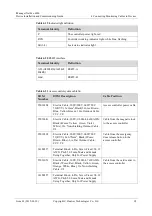
Table 4-12
Cable connections for the fingerprint and card reader with a keypad
Conversion Cable
Wire of the Network
Cable
Access Controller
Terminal
Red wire
Pin3
R-12V
Green wire
Pin4
R-D0
White wire
Pin5
R-D1
Black wire
Pin8
R-GND
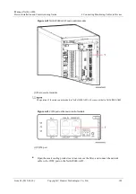
Connect one end of another network cable to the RS485 port on the fingerprint and card
reader with a keypad, and connect the other end of the network cable to the
non-energized COM port on the ECC500 collector. The following table shows the pin
mapping for the RS485 port and the COM port.
Table 4-13
Pin mapping for the RS485 port and the COM port
RS485 Port on Fingerprint and Card Reader with a
Keypad
COM Port on ECC500
Collector
Pins
Definition
Pins
Pin1
485A (brown)
Pin1
Pin2
485B (white)
Pin2
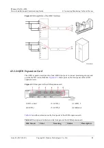
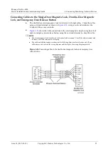
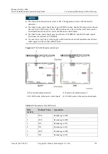
Connecting Cables to the Card Reader with a Keypad
The following figure shows the cable connections to the access controller and card reader
with a keypad, using the cord end terminal to crimp the cable.
Figure 4-35
Connecting cables to the card reader with a keypad

