background image

100/180 mm PAPERLESS GRAPHIC RECORDER: USER GUIDE

HA028910

Issue 13  Sep 16

User Guide

Page 261

7.2.4  SCREEN CREATION EXAMPLE (Cont.)

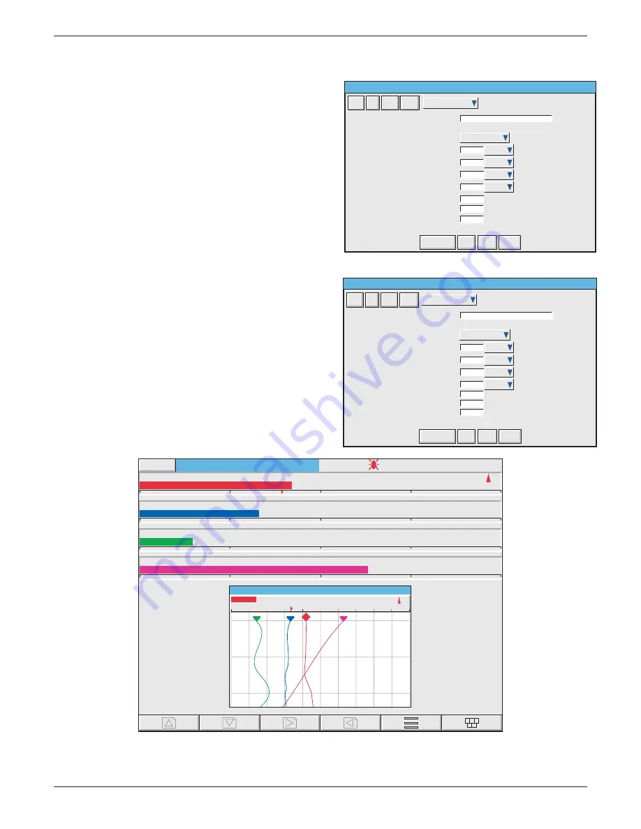
12  Touch the component picklist fi eld, and highlight 

the topmost ch_hor_bar... fi eld.

13.  In the Identifi er fi eld, enter the name ‘Bar 1’ using 

the pop-up keyboard. (To enter numbers, touch 
the ‘Numeric’ tab under the keyboard, then touch 
the required number.)

14.  The channel number is as required 
15.  Touch the width fi eld and enter a value of 100.
16.  Touch the height fi eld and enter ‘10’
17.  Press ‘Save’

18. Touch the component picklist fi eld and select 

another bargraph.

19.  In a similar way to that described for Bar 1 
 

a)  enter the identifi er ‘Bar 2’


b)  select Channel 2 from the picklist


c)  enter  a Y value of 12


d)  enter width = 100%; height = 10%.

20.  Similarly confi gure Bar 3 and Bar 4, using the ap-

propriate Y values (24 and 36) and Channel selec-
tion (3 and 4).

21   Finally, press ‘Save’, then ‘Close’, to reveal the 

display page.

Group 1 . User Screen 1

Batch Number:050822.010

14:01:24

22/08/05

Engineer

1.0000

0.0000

0.4187

˚C

Channel 1

1.0000

0.0000

0.3316

˚C

Channel 2

1.0000

0.0000

0.1427

˚C

Channel 3

1.0000

0.0000

0.6293

˚C

Channel 4

13:59:02

22/08/05

0.0000

0.2000

0.4000

0.6000

0.8000

1.0000

Channel 1

0.4187

˚C

Group 1

Identifier

Component Property Editor - Screen 1

Last Error

X Position

Y Position

Width

Height

Background Colour

Component Type

Channel Horizontal Bargraph (ch_hor_bar)

Channel

Forground Colour

Draw Order

Add

Del

Copy

Paste

ch_hor_bar_4.2

Bar 2

0

%

-1

10

100

12

%

%

%

2) Channel 2

-1
-1

Goto Canvas

S a v e

Close

M o r e . . .

ch_hor_bar_2.2

Identifier

Bar 1

Last Error

X Position

0

%

Y Position

Width

Height

Foreground Colour

Component Type

-1

10

100

0

%

%

%

Channel Horizontal Bargraph (ch_hor_bar)

Channel

1) Channel 1

Background Colour

-1

Draw Order

20

Add

Del

Copy

Paste

Component Property Editor - Screen 1

Goto Canvas

S a v e

Close

M o r e . . .

Содержание 6100A

Страница 1: ...6100A 6180A User Guide 6100A 6180A Paperless graphic recorder Versions 5 and later HA028910 13 September 2016 ...

Страница 2: ......

Страница 3: ......

Страница 4: ......

Страница 5: ...AVE COMMS 281 9 ANALOGUE OUTPUT OPTION 333 10 EVENT INPUT OPTION 335 11 TRANSMITTER POWER SUPPLY 336 12 ASCII PRINTER OUTPUT OPTION 339 13 PORTABLE CASE OPTIONS 351 14 REMOTE CJ BLOCK OPTION 364 15 THERMAL UNIFORMITY SURVEY TUS OPTION 374 ANNEX A SPECIFICATION 378 ANNEX B REFERENCE 388 ANNEX C WEB SERVER DETAILS 418 INDEX 422 EFFECTIVITY This manual refers to recorders fit ted with software versio...

Страница 6: ... ARCHIVE ACTIVE 13 3 PROCESS VARIABLE DISPLAY 14 TRUNCATION OF NUMERIC VALUES 14 CURRENT TRACE ALARM ICONS 15 3 1 STATUS BAR 15 3 1 1 Current access level 15 3 1 2 Page name 15 3 1 3 Alarm indication 16 INSTRUMENT ALARM 16 CHANNEL ALARM 18 CHANGE BATTERY 18 DISK ICON 18 FTP ICON 18 CONFIGURATION LOCKED INDICATOR 18 TRIAL MODE INDICATOR 18 3 1 4 Summary menu 19 INSTRUMENT ALARM SUMMARY 19 ACK ALL A...

Страница 7: ...4 2 5 Import screen 56 4 2 6 Export screen 56 4 2 7 Import User Linearisation 57 4 2 8 Export User Linearisation 57 4 2 9 Import printer driver 57 4 3 CONFIG KEY 58 4 3 1 Instrument configuration 63 INSTRUMENT NAME 63 NORMAL SAVER DISPLAY 63 SAVE AFTER 63 MODBUS ADDRESS 63 MODBUS SECURITY DISABLED 63 COMMS CHANNEL TIMEOUT 63 PRESET HOUR 64 PRESET MINUTE 64 DISABLE WARNING DIALOGS 64 SHOW OPERATOR ...

Страница 8: ...PE 78 SETPOINT SOURCE 78 PARAMETERS 79 HYSTERESIS EXAMPLE 79 RATE OF CHANGE ALARM EXAMPLE 79 JOB NUMBER 81 CATEGORY 81 WHILE ON 81 ALARM MESSAGES 81 4 3 4 Views Configuration 82 HOME TIMEOUT 82 HOME GROUP 82 SCOPE 82 GROUP 83 DISPLAY ENABLE 83 HOME PAGE 83 DISPLAY MODE ENABLING 83 4 3 5 Archive configuration 85 COMPRESSION 86 FLASH SIZE 86 SHORTEST TREND HISTORY DURATION 86 CSV CHECK BOXES DATE TI...

Страница 9: ...DRESSING 135 4 3 12 Totalisers 138 INTRODUCTION 138 4 3 13 Counters 143 INTRODUCTION 143 CONFIGURATION 143 CONFIGURABLE PARAMETERS 143 COUNTER MODBUS ADDRESSING 144 4 3 14 Timers 147 INTRODUCTION 147 CONFIGURATION 147 Configurable parameters 148 SELF START EXAMPLE 148 4 3 15 Connections 149 INTRODUCTION 149 INSTALLATION 149 CONFIGURATION 150 4 3 15 CONNECTIONS Cont 151 CONFIGURATION PARAMETERS 151...

Страница 10: ...TS 201 ACKNOWLEDGE ALARMS 201 EDIT MATHS CONSTANT 201 RESET MATHS 201 PRESET TOTALISERS 201 PRESET COUNTERS 201 START RESET TIMERS 201 SET CLOCK 201 ADJUST I O 201 ARCHIVING CONTROL 202 SAVE RESTORE 202 PASTE DELETE FILES 202 FULL CONFIGURATION 202 FULL SECURITY 202 BATCH CONTROL 202 CAN SIGN 202 CAN AUTHORIZE 202 PERFORM UPGRADES 202 EVENT PERMISSION 1 202 EVENT PERMISSION 2 TO 5 202 EDIT OUTPUT ...

Страница 11: ...4 6 1 Clock 220 4 6 2 Locale 220 LONG DATE FORMAT 220 4 6 3 Upgrade 221 4 6 4 Input adjust 222 4 6 5 Output Adjust 224 4 6 6 Master Comms Diagnostics 224 4 6 7 Ethernet Diagnostics 224 4 6 8 Copy 225 CONFIGURABLE PARAMETERS 226 COPY RULES 226 4 6 9 Job search 227 SEARCH RESULTS 227 4 6 10 Customise 228 FONT SIZE EXAMPLES 229 4 6 11 About 230 INSTRUMENT VARIANT 230 CONFIG REVISION 230 LAST UPDATED ...

Страница 12: ...s line 251 6 6 4 Error messages 252 NETWORK CONNECTION HAS TIMED OUT 252 UNABLE TO CONNECT TO HOST 252 UNABLE TO RESOLVE HOSTNAME 252 FAILED TO AUTHENTICATE THE USER NAME 252 MAXIMUM NUMBER OF BRIDGE SESSIONS ALREADY RUNNING ON 252 THERE APPEARS TO BE NO FREE DISK SPACE ON 252 YOU ARE ALREADY RUNNING A FULL BRIDGE SESSION 252 YOU ARE AUTHENTICATING FULL BRIDGE 252 7 SCREEN BUILDER 253 7 1 INTRODUC...

Страница 13: ... 7 6 ERROR CODES 280 8 MODBUS TCP SLAVE COMMS 281 8 1 INSTALLATION 281 8 2 INTRODUCTION 281 8 2 1 Function Codes 281 DIAGNOSTIC CODES 281 EXCEPTION CODES 282 8 2 2 Data types 282 DATA ENCODING 282 8 2 3 Invalid multiple register writes 282 8 2 4 Security 282 TO SEND A LOGIN REQUEST 285 8 2 5 Text messages 287 LONG MESSAGES 287 8 3 ADDRESS MAP 289 8 4 ADDRESS ALLOCATION 291 8 4 1 Instrument data 29...

Страница 14: ...ANNEL 2 323 CHANNEL 3 324 CHANNEL 4 324 CHANNEL 5 325 CHANNEL 6 325 CHANNEL 7 326 CHANNEL 8 326 CHANNEL 9 327 CHANNEL 10 327 CHANNEL 11 328 CHANNEL 12 328 8 4 9 Permanent ID table 329 8 5 DATA TRANSMISSION 329 FUNCTION CODES AND EXCEPTION CODES 329 TEXT STRINGS 329 8 5 1 Function code 03 330 REQUEST 330 RESPONSE 330 EXCEPTION RESPONSES 330 8 5 2 Function code 04 331 8 5 3 Function code 06 331 REQU...

Страница 15: ...S FROM 341 MESSAGES TO PRINT 341 12 3 2 Reports configuration 342 REPORT 342 DESCRIPTOR 342 NUMBER OF FIELDS 342 FIELD N TYPE 342 STYLE 343 POINT 343 LINE FEED 343 12 3 3 ASCII Input Filtering 343 Text Filters 343 Configuration 343 12 4 IMPORTING PRINTER DRIVERS 346 12 5 REPORT EXAMPLE 347 12 5 1 Group Configuration 347 GROUP NUMBER 1 347 12 5 2 Channel configuration 347 CHANNEL 1 347 CHANNEL 2 34...

Страница 16: ...G 367 14 2 3 Specification 370 14 3 SMALL FRAME RECORDER 371 14 3 1 Introduction 371 14 3 2 Signal wiring 371 SIGNAL WIRING 371 14 3 3 Specification 373 15 THERMAL UNIFORMITY SURVEY TUS OPTION 374 15 1 PRE CALIBRATION AND POST CALIBRATION ENABLE 374 Pre calibration 374 Post calibration 374 15 2 INPUT ADJUST 375 ADJUST PROCEDURE 376 15 3 CHART MESSAGES 377 15 4 OTHER ITEMS 377 Annex A SPECIFICATION...

Страница 17: ...CREEN CLEANING 393 B2 2 MAINTENANCE SCHEDULE 394 B2 2 1 Battery replacement procedure 394 B2 3 FLAP RELEASE 396 B3 OPTION ENABLING 397 B4 COLOUR SELECTION 397 B5 TCP PORT NUMBERS 400 B6 ASCII CHARACTERS FOR SERIAL COMMS 401 B7 TIME ZONE INFORMATION 402 B8 HISTORY MAINTENANCE OPTION 403 B8 1 KEYCODE EXTRACTION 403 B8 2 ERASING HISTORY 403 B9 MENU STRUCTURE 404 Annex C WEB SERVER DETAILS 418 C1 INTR...

Страница 18: ...100 180 mm PAPERLESS GRAPHIC RECORDER USER GUIDE HA028910 Issue 13 Sept 16 User Guide Contents Page xiv This page is deliberately left blank ...

Страница 19: ...he mains supply fuse within the power supply is not replaceable If it is suspected that the fuse is faulty the manufacturer s local service centre should be contacted for advice 4 Whenever it is likely that protection has been impaired the unit shall be made inoperative and se cured against accidental operation The manufacturer s nearest service centre should be contacted for advice 5 Any adjustme...

Страница 20: ...tative contacted for instructions After the recorder has been removed from its packing the packing should be examined to ensure that all accessories and documentation have been removed The packing should then be stored against future transport requirements 2 INSTALLATION 2 1 MECHANICAL INSTALLATION Figures 2 1a and 2 1b give installation details for the small and large frame cases respectively Not...

Страница 21: ...Cont Figure 2 1a Mechanical installation details small frame unit 0 1 2 2 34 0 1 01 2 34 5 6788 6788 9 013738 2 37334 5 2 64 789 5 2 68 7893 0 0 1 0 A BC 2 68 7893 5 2 64 789 D E F 633 G D 633 0 E 7HI F 0 0 6JK L 1 M6694 0 0 E N M3 94 O 1 E N MPP 7 0 Q 364 7 M39K4 J4 68M 68 9R 6JK L S 2 J M4 9 T S 0 0 U 5 V ...

Страница 22: ...2 INSTALLATION Cont Figure 2 1b Mechanical installation details large frame unit GWX Y XZ AGOOV GZ OV 2 2 34 0 1 0 E F 0 0 01 2 34 5 73 73 9 013738 2 37334 x y MRM MRM D E F G D M66 M 89R8 MP9J3 MKR M6 MKR L 1 2 M4 76 5 2 6M94 7894 0 0 1 0 A BC 2 6M94 7894 5 2 M4 76 L S 1 2 M4 9 T S 0 0 U 5 V ...

Страница 23: ...0 35Nm Figure 2 2 1a Connector locations small frame units Ethernet RJ45 Safety Earth M4 Serial comms option USB Ports option USB 1 USB 2 Port 1 Port 2 L N E Mains supply connection Input channels 1 to 6 Option slot 1 Option slot 2 Option slot 3 Option slot 4 L N E Mains supply connection Input channels 1 to 6 Option slot 1 Option slot 2 Option slot 3 Option slot 4 Input channels 7 to 12 Serial co...

Страница 24: ...ge 6 2 2 1 SIGNAL WIRING Cont Figure 2 2 1b Connector locations large frame units X 6 K X 6 X K 6M X 6 K X 6J 6P X 6R M3 X 6 K X M4 J8 X J6 J X 6 K X JK 3M X 3J 3P T C 0 J T C 0 3 T C 0 6 T C 0 M Z 0 T C 0 R T C 0 K T C 0 P T C 0 4 T C 0 7 O Z V 7 5 Y L 7 V H_34 Y 6 Y M L 6 L M U 5 V 7 3 ...

Страница 25: ...ive 0 8 to 30 V Digital inputs voltage levels Not channels 1 7 13 etc V V I 30V Vin 0 8V active 2V Vin 30V not active 0 8 Vin 2V not defined Vin User 0V V V I Shunt assembly V V I V V I Attenuator assembly 200 to 200 V dc 20 to 20 V dc Thermocouples dc millivolts DC milliamps 1 2 3 4 5 6 7 8 9 10 11 12 13 14 15 16 17 18 19 20 21 22 V Cold junction Input board pinouts Channels 1 7 13 19 25 31 37 43...

Страница 26: ...3 4 5 6 7 8 9 10 11 12 13 14 15 16 17 18 19 20 21 22 Rly 1 c c Rly 2 no c Rly 3 no c no no Rly 4 Four normally open relays Rly 1 c c Rly 2 no c Rly 3 no c no no Rly 4 c no Contacts shown in power off alarm state Relay outputs Max number of boards 4 for small frame or 9 for large frame 1 2 3 4 5 6 7 8 9 10 11 12 13 14 15 16 17 18 19 20 21 22 1 2 3 4 5 6 C 1 2 3 4 5 6 C Event inputs max 4 option boa...

Страница 27: ...r recorders fitted with the isolated transmitter power supply option The low voltage supply option is terminated at a three pin connector plug mounted on recorder socket on supply cable as shown in figure 2 2 2 The option allows the use of ac or dc supplies with the follow ing characteristics AC 20 to 42V RMS 45 to 400 Hz DC 20 to 54V See warning above Power 50 W max V or ac Earth 0V or ac Figure ...

Страница 28: ...more fingers under the flap handle and pull it outwards and down figure 2 3 A lockable version of the flap is available see section 2 4 for details Located behind the flap are from left to right 1 a stylus press to eject 2 a slot for a Compact Flash or Secure Digital SD card 3 a USB port usbfront USBFront Stylus storage SD or Compact Flash card Door lock option Stylus storage SD or Compact Flash c...

Страница 29: ...ove Media facility described in section 3 1 4 Summary menu be used to ensure that it is safe to remove the memory device For recorders fitted with a lockable flap see also section 2 4 Figure 2 3 2a SD card details Figure 2 3 2b Compact Flash card details LED INDICATORS Three LED indicators are located above the card slot as shown in figure 2 3 2c below SD card Push in Push out Eject button Press t...

Страница 30: ... description below applies only to Archive data 2 4 1 Flap lock operation ARCHIVE INACTIVE 1 Touch the root menu or alarm status area at the top of the screen 2 Touch the Unlock Flap key figure 2 4 1a 3 Archiving is suspended the internal solenoid releases the catch to allow the flap to be opened and a pop up message appears OK to remove archive media figure 2 4 1b 4 After approximately five secon...

Страница 31: ... that no attempt will be made by the recorder to write to the device until Resume Archiving is operated b If the Cancel key is not operated the warning message remains on the screen then when the archive is complete archiving is automatically suspended and the flap unlocks again for five seconds allowing the memory device to be removed The message on the screen changes to OK to remove archive medi...

Страница 32: ...10 Customise TRUNCATION OF NUMERIC VALUES If the amount of space on the display page is insufficient to display the full width of the process variable or scale value then the displayed value is rounded down and the number of decimal places reduced If the width is still too restricted the value is displayed in scientific format or if this is still too wide the final visible character of the integer...

Страница 33: ...change Falling Absolute low Absolute high Deviation In Out Horizontal scales Vertical scales Rate of change No indication No indication R d d d d R For Deviation alarms R Reference d deviation Scale symbols Table 3 Alarm icons 3 1 STATUS BAR This appears across the top of the display and contains the items described below 3 1 1 Current access level There are four access levels available Logged out...

Страница 34: ...s too infrequent The recorder effectively switches to Automatic section 4 3 5 to ensure that data is not lost FTP Primary Server Failure This error is set if the recorder fails after two attempts to establish communications with the primary server as defined in Archive Con figuration section 4 3 5 After the second attempt has failed the Secondary server is tried FTP Secondary Server Failure This e...

Страница 35: ...storage device full Becomes active only when an Archive is in progress SNTP server failure This error is set if a the year received from the server is 2001 or 2035 or b the configured SNTP server cannot be accessed Time synchronisation failure Set if 5 or more Time change events are caused by the SNTP server within 24 hrs A Time change event occurs whenever the recorder time is found to be more th...

Страница 36: ...otes 1 The icon appears only when a memory device is present AND when that memory device has been selected in the Archive to media selection in archive configuration section 4 3 5 For example if a memory stick is inserted in usbfront but Archive to Media is set to mediacard then the disk icon appears only if a suitable card is present in the mediacard slot 2 When a disk is inserted into a USB flop...

Страница 37: ...Summary Ok Maths Channel Failure Printer Error This contains a list of the currently active instrument alarms For a list of possible alarms and their defini tions see section 3 1 3 above ACK ALL ALARMS Figure 3 1 4c Ack all Alarms display Ack all Alarms Yes No Confirm acknowledge of alarms Yes confirms all active unconfirmed alarms This page can also be displayed by touching an alarm in the alarm ...

Страница 38: ...wledged See section 4 3 3 for a description of alarm types and actions 3 There are no time or history components associated with the Alarm Summary If Alarm mes sages have been enabled in the relevant group s configuration section 4 3 2 then alarm initia tion acknowledgement times and dates can be found from the trend and trend history displays described in section 3 4 or in Message log described l...

Страница 39: ...ptions key section 3 2 the Ack Group Alarms key and finally Yes in the resulting pop up confirmation box Figure 3 1 4e below attempts to show this process Figure 3 1 4e Group Alarm acknowledgement ALL ALARMS To acknowledge all active alarms touch e g the channel alarm icon at the top of the screen From the resulting Summary menu select Ack all Alarms then finally touch Yes in the resulting pop up ...

Страница 40: ...arms Alarm Summary Batch Summary Message Log Unlock Flap Instrument Alarm Summary Summary Touch Alarm area e g channel alarm symbol Batch Summary Group Mode Group names Batch start time and date Elapsed time Batch Field 1 text Batch Field 1 values ColourMix1 25 04 06 09 12 18 00 02 41 Batch Number 060425C1 ColourMix2 25 04 06 08 45 13 00 29 46 Batch Number 060425M1 ColourMix3 25 04 06 08 50 07 00 ...

Страница 41: ... batch SORT If Sort is Off default the groups appear in Group number order with Group 1 at the top and group 12 at the bottom The key legend is Sort ON If Sort is On those groups with batches running appear in group number order at the top of the list fol lowed by any remaining groups also in group number order The key legend is Sort OFF HIGHLIGHT If Highlight is Off default then all groups text a...

Страница 42: ...ry Summary Group 5 Batch number 050405A12 09 06 22 05 04 05 Engineer Message Log Group name All Messages All History 05 04 05 09 06 18 Alarm s on 1 1 05 04 05 09 06 18 Operator s name Andrew 05 04 05 09 06 18 Customer FishesRus 05 04 05 09 06 18 Batch number 020205A12 05 04 05 09 06 18 Config Revision 682759 Security Revision 746261 05 04 05 09 06 18 Batch start Engineer 05 04 05 08 50 30 Configur...

Страница 43: ...es Displays only batch messages including Config and Security Revisions if either Auditor option is enabled Logins Lists only changes in login Signings This list contains only notes messages etc that have been signed and authorized This category is used only when Require Signing and Require Authorization is are enabled in the Security Management menu see section 4 4 for more details Audit trail Th...

Страница 44: ...tory whilst either Earlier Messages or Later Messages is highlighted calls the current History page 2 If the Option Menu has timed out leaving a message highlighted and the option key is oper ated then this is equivalent to reselecting the message 05 04 05 09 06 18 Alarm s on 1 1 05 04 05 09 06 18 Operator s name Andrew 05 04 05 09 06 18 Customer FishesRus 05 04 05 09 06 18 Batch number 020205A12 ...

Страница 45: ...is safe to do so Touching the key results in either an OK to remove archive media or a DO NOT REMOVE Archive Me dia message as appropriate See figure 3 1 4i CAUTION Removal of memory devices such as SD cards or Compact Flash cards whilst archiving is taking place can lead to permanent irreparable damage to the device rendering it unusable Figure 3 1 4i Remove archive media messages OK to remove ar...

Страница 46: ...hannel cycling on and off etc according to context Root Calls the Root Menu as described below To quit the Root menu touch the root key again ROOT MENU KEYS Home Causes a return to the Home page from any page in the recorder As delivered the Home page is the Group 1 vertical trend display as depicted in figure 3 but this can be edited in Config Views to be any of the other available groups display...

Страница 47: ...hrough groups in ascending group number order The left arrow key can be used to scroll through groups in descending group number order Figure 3 2 1a Root menu with Goto View sub menu Home Operator File Goto View Goto Group Message Log Horizontal Trend Vertical Bargraph Alarm Summary Vertical Trend Circular Trend Numeric Page User Screen 2 Horizontal Bargraph User Screen 1 User Screen 3 More A disp...

Страница 48: ...dia menu but in this case the user must select an alarm summary group from a pop up Goto Group menu See section 3 1 4 for more details of the alarm summary page MESSAGE LOG The Root menu Goto View Message log key calls the Message Log page for the current group to the screen Alternatively Message Log can be selected from the Alarm Message and Media menu but in this case the user must select a Grou...

Страница 49: ...ible Only Archive Login security and the System About functions can be accessed via the root menu Limited or full access can be permitted from Engineer level Operator No access to recorder configuration is possible until access permissions have been set up Section 4 4 1 describes how limited or full access can be permitted by an operator with Engineer level access Engineer Accessed initially by en...

Страница 50: ...ator page rather than returning to the home page once login has been achieved 3 Figure 3 3 1a shows Login by user list which is the default method If either Auditor option and or the Security management option is enabled an alternative procedure is possible where each user has to enter a name and associated password i e there is no list of users access levels to choose from See section 4 4 2 Manag...

Страница 51: ... as long as the key is active Shift Once the shift key has been pressed the next entered letter appears as a capital subse quent letters are in lower case Caps When pressed all subsequent letters appear as capital letters until the Caps key is oper ated again BSpc This backspace key deletes character to the left of the cursor Ovr If selected the next entered character replaces overwrites the exist...

Страница 52: ...1c Alternative keyboards Symbols Numeric Text String Alphabet Shift Caps BSpc Ok Cancel Alphabet 2 Ovr Symbols Numeric Text String Alphabet Shift Caps BSpc Ok Cancel Alphabet 2 Ovr Numeric Text String Alphabet Shift Caps BSpc Ok Cancel Alphabet 2 Ovr Symbols Ä Å Á À Æ Ç É È a Ë Ê Í Ì Ï Ó Ò Ô Î Ö º Ü Ú Ù Û Ñ ÿ β Γ δ α τ φ Ω Σ θ µ π η ε _ 3 2 7 8 9 4 5 6 1 2 3 0 E ...

Страница 53: ... touch the faceplate 4 Group faceplates are not displayed in trend history mode 5 Operation of the Root Goto View Message Log key section 3 2 1 when in history mode dis plays a message log page containing messages which occurred at or near the selected cursor time 6 With A B switching selected traces are displayed with the A or B span zone colour settings etc obtaining at the cursor time See secti...

Страница 54: ... diamond shaped pen icon and by its descriptor digital value and scale being displayed on a faceplate across the full width of the screen above the chart If a channel is included in the display group but its status is not good for some reason then its pen icon is hollow Faceplates for all the group channels can be displayed by using the Faceplates On Off key in the option menu If selected On facep...

Страница 55: ... 59 05 04 05 11 52 04 05 04 05 11 49 24 05 04 05 11 46 44 05 04 05 05 04 05 11 47 51 Alarms s on 3 1 05 04 05 11 51 33 Alarms s off 3 1 Home Trend display mode E n g i n e e r Preparing History please wait 04 05 04 11 49 54 Cursor time date Touch faceplate to increment channel 800 00 720 00 5 6 0 0 0 4 8 0 0 0 Faceplate for current channel Touch and release face plate to increment channel or touch...

Страница 56: ...here are two faceplates associated with this display mode one above the chart showing the current channel s descriptor and its digital value the other to the right of the chart showing a bargraph rep resentation of the current channel s value together with a scale showing the low and high range values for the channel Touching either of these faceplates causes the current channel number to incremen...

Страница 57: ... 21 30 06 04 05 E n g i n e e r Channel 1 7 0 0 8 7 C 400 800 14 16 20 06 04 05 14 13 40 06 04 05 14 11 00 06 04 05 06 04 05 12 02 20 Alarm s off 2 1 View Messages 06 04 05 12 02 20 Batch Number 050406 3 06 04 05 11 11 41 Config Revision 218 Security Revision 3 06 04 05 11 11 34 Batch start Engineer 06 04 05 11 09 34 Alarm s on 1 1 06 04 05 11 09 26 Alarm s off 1 2 06 04 05 11 07 41 Alarm s on 1 2...

Страница 58: ...ion 4 3 2 The user can select Rotate or New Chart ROTATE In the following description the word segment is used interchangeably with Major chart division The number of Major chart divisions is a function of the selected chart speed as described in Group Configu ration section 4 3 2 With Rotate selected the traces start one major chart division anti clockwise from the top of the chart and trace cloc...

Страница 59: ...r Trend normal view with faceplates 06 04 05 10 00 10 05 10 10 10 15 10 20 10 25 10 30 10 35 10 40 10 45 10 50 10 55 Group name 11 05 33 06 04 05 Logged out Full Screen Furnace 1 Temp 13 1500 0000 0 0000 0 0000 1500 000 06 04 05 10 10 14 08 02 10 15 06 04 05 2 10 20 06 04 05 10 25 06 04 05 10 30 06 04 05 10 35 06 04 05 10 40 06 04 05 10 45 06 04 05 10 50 06 04 05 10 55 06 04 05 11 00 06 04 05 11 0...

Страница 60: ...he message bar at the bottom of the screen displays the latest message If an up arrow appears at the right hand end of the bar there is more than one message Touching the message bar calls a View Messages window detailing previous messages See the de scription in section 3 4 2 for more details FULL SCREEN DISPLAY As shown in figure 3 4 3c below this maximizes the chart diameter leaving only the ch...

Страница 61: ...ive recording results in two traces per trend as in other trend display modes 2 For successful circular trend display Circular Settings must be enabled for the relevant group sec tion 4 3 2 and Circular Trend must be enabled for the group in Views configuration section 4 3 4 If Circular Trend is enabled but Circular Settings is disabled then although the circular chart will appear it is unlikely t...

Страница 62: ... off This feature is available for vertical trend circular trend and vertical bargraph displays only To call the horizontal bargraph display mode use the down arrow key Alternatively any one of the ena bled display modes section 4 3 4 can be selected using the Root Menu Goto View key Trend history mode is not available from this display mode FACEPLATES ABOVE THE BARS See figure 3 4 4a As the numbe...

Страница 63: ...487 39 C Channel 3 235 68 C 0 00 400 00 Channel 4 378 99 C 0 00 1 00 Channel 5 0 49V 0 00 400 00 80 40 80 40 40 0 0 40 0 0 1 0 0 0 1 0 0 0 80 40 80 40 40 0 0 40 0 0 1 0 0 0 1 0 0 0 500 0 500 0 500 0 500 0 500 0 500 0 100 0 100 0 100 0 100 0 100 0 100 0 Group name 11 49 37 06 04 05 Logged out 487 39 C 235 68 C 378 99 C 0 49 Channel 6 0 85 Channel 7 689 43 C Channel 8 483 72 C Channel 9 255 81 C Cha...

Страница 64: ...channels in the display group double column for more than 12 channels For small frame recorders only the single column mode is employed with a scroll bar when necessary 2 For large frame recorders up to 26 points can be displayed simultaneously for small frame recorders the maximum is 5 points In either case if more points are enabled than can be displayed within the height of the screen a vertica...

Страница 65: ... 04 05 Logged out Channel 1 400 00 800 00 700 87 C Channel 2 400 00 800 00 Channel 3 700 87 C Channel 4 0 00 400 00 Channel 5 0 00 1 00 700 87 C Channel 6 Channel 7 400 00 800 00 700 87 C Channel 8 400 00 800 00 Channel 9 0 00 400 00 700 87 C Channel 10 0 00 400 00 Channel 11 0 00 1 00 700 87 C Channel 12 0 00 1 00 Channel 13 0 500 700 87 C Channel 14 0 500 Channel 15 0 500 700 87 C Channel 16 0 5...

Страница 66: ...e from this display mode A further operation of the down arrow key returns to Vertical Trend Display mode described in section 3 4 1 above or if user screens are fitted and enabled to the first user screen section 7 Alternatively any one of the enabled display modes section 4 3 4 can be selected using the Root Menu Goto View key Figure 3 4 6a Numeric display mode 1 to 5 channels example Note Figur...

Страница 67: ... Channel 1 Channel 3 Channel 5 Channel 2 Channel 4 Channel 6 V 487 39 378 99 0 85 235 68 0 49 Logged out 700 87 Group name Channel 1 700 87 Channel 2 487 39 Channel 3 235 68 12 04 13 06 04 05 Logged out Channel 4 378 99 Channel 5 0 49V Channel 6 0 85V Channel 7 689 43 Channel 8 483 72 255 81 Channel 10 375 01 Channel 11 0 53V Channel 12 0 79V Channel 13 235V Channel 14 235V Channel 15 235V Channel...

Страница 68: ...text of up to 120 characters spaces are also counted as characters Press Ok when finished 5 View the note and a press the Ok button to enter the note OR b re touch the text area to edit the note OR c press the Cancel key to quit note entry Figure 3 5 Access to Note entry page Note Operator Note Option Key Option Menu Batch Note Faceplates On Off Enter History Channel Cycling Off 00 0A 8D 00 20 A0 ...

Страница 69: ... passwords and access level permissions Network Section 4 5 This area sets up the IP address host names etc used in FTP transfer Bridge and SNTP applications System Section 4 6 Allows a Time and date to be set Clock b Language date time format time zone and daylight saving start and finish dates to be set Locale c Software upgrades to be carried out Upgrade d Input channels to be adjusted for erro...

Страница 70: ...a lockable flap see also section 2 4 Figure 4 1 1 Local archive configuration Archive System Save Restore Config Security Network Section 4 1 2 Last Archive Archive Last Hour Bytes Bytes Archive Last Day Archive Last 7 Days Archive Last 31 Days Archive All Suspend Archiving Cancel Archive Bring Archive Up To Date Archive Transfer Media Size Free Space Inactive 31954944 28786688 13 09 2005 11 02 42...

Страница 71: ... in the Archive transfer window Below the selection buttons are a number of status windows relating to the selected memory device Media Full is an estimate based on the current configuration of when the memory device will become full The meanings of the Media Size and Free Space values are self evident If automatic archiving is active section 4 3 5 then automatic and manual archives will operate o...

Страница 72: ...ime and can access those items of recorder configuration that are associated with the user s login For successful connection Connect from Remote must be enabled and the Remote user name and Remote pass word must be defined in one of the accounts all in the Security access menu section 4 4 1 Notes 1 In order to view history files when accessing the instrument remotely the recorder s address the Rem...

Страница 73: ...or more details Once the correct folder is open either select an existing file or enter a new filename by touching the FileName window and entering the name using the pop up keyboard s as de scribed in section 3 3 1 above Operation of the Save Restore key initiates the action Figure 4 2b Typical volume contents page Hide user Type Name cal config lib Folder Folder Folder Save Cancel FileName Filte...

Страница 74: ...s active part of Security Management configuration section 4 4 2 Security Data is not selectable either for Restore or for New below 4 If the file to be restored has been created using C Edit software each of the characters used in the file name must lie within the unicode range 0 to 255 or the file name might not be dis played correctly 4 2 3 New Touching this item causes the factory entered defa...

Страница 75: ...r X is the input value and Y is the linearised value corresponding to X See section 4 3 9 for full details Note Imported linearisation tables will not become effective until after the next configuration Apply operation 4 2 8 Export User Linearisation Similar to Import user Linearisation above the Export Linearisation feature allows linearisation tables created in the recorder to be exported either...

Страница 76: ...ration menus 2 If an option is not fitted it does not appear in the above list When making changes to the configuration the name of each changed parameter is displayed in red instead of the normal black until the Apply Discard key has been operated For example in channel configuration if a thermocouple were to be changed from Type J to Type K Lin Type would appear in red until the Apply key is ope...

Страница 77: ...Type K Range Low 0 C Range High 100 C Range Units C Scaled Offset 0 V Filter None Break Response None Cold Junction Type Off Descriptor TurbineTempA Spanned Channel Number 1 TurbineTempA 07 04 05 08 46 45 Scale Type None A B Switching Zone Low 0 Zone High 100 Groups Section 4 3 2 Views Section 4 3 4 Home Time out Home Group Scope Group Display Enable Home Page Vertical Trend Horizontal Trend Verti...

Страница 78: ... A88 B12 5 3D 3 3 J 4 Q Y 4 Q Y E2 5 J1 512 1 B 2 518 5 0 5 5 1 2 3 3 G HD E2 5J1 H 51 G 3 G 3 E2 5J1 H A88 B12 5 E2 5 J1 512 1 2 V 1 7WHW_D A5 1I 2 I L 2 5 F 16 51 9 5U I 2 V 1 7WHW D A88 B12 5 0 1 0I 51 1a1 6 Q 8 3G3W3 J 9 B 2 518 5 0 3 J 9 K1 2 Q 8 b 9 b 16 K Y B 1 B161 2 G F 5 A 5 5 3 4 c 5 3 F 6 5 A 1 GP F 3 O d 3 d K 2 5 3D 0 3 HGWPO L 2 9 K1 2 0 5 51 Q 8 5 5 1 5I 3 E 1 2 K1 2 16 P A 91 1 6 ...

Страница 79: ... 0 EIA232 Serial 1 9600 1 Even Star TSP600 Star TSP600 1 Not Responding 1 Group 1 ASCII Printer Apply Discard 250 Baud Rate Parity Data Bits Timeout First Start Char Second Start Char First End Char Second End Char Group 1 Group 2 Group 3 Group 4 Group 5 Group 6 19200 1 None 8 ms 0 13 Link Error Count 0 0 10 Reset Error Count Protocol ASCII input Port Serial 1 Connection EIA232 Stop Bits ASCII Inp...

Страница 80: ... Write Slave Parameter Point Type Point Number Descriptor Source Default Allow Constant Edits Disable Retries Send On Power Up On Error Write Default Master Comms 1 Write 1 OK 1 Furn 1 Recorder Alarm setpoint 2 Channel 1 Write 1 Channel 1 0 Report Descriptor Number of Fields Field 1 Type Style 1 Report 1 1 Date Time Normal Report 1 Apply Discard 0 b 7 39J96P 6 J U E a U 1 T 7 39J9MM Mail Server Po...

Страница 81: ...minutes between 1 and 99 inclusive which are to elapse after a screen operation before the screen brightness changes from normal to saver Default is 30 minutes MODBUS ADDRESS Allows a Modbus address between 1 and 247 to be set up for use when the instrument is acting as a Modbus slave MODBUS SECURITY DISABLED When using MODBUS it is possible by checking this field to allow a host computer to acces...

Страница 82: ...nt alarm messages from appearing on the screen SHOW OPERATOR NOTES LIST Enabling this field produces a list of 13 entries which can be used in Operator Notes The first entry is the MAC address of the recorder and is not editable The remaining 12 entries of up to 60 characters each are freely editable Any one of these predefined notes can be selected as described in section 3 5 by touching the Oper...

Страница 83: ...rid Divisions Major 5 1 Apply Discard Alarm Message Recording Speed Recording Interval Archive to Media Enable Archive via FTP Enable Trend History Duration Recording Enable Ack Message TurbineTempA TurbineTempB Enabled Etc 1 1 200 mm hr s List of all available points input channels maths channels totalisers etc 314 36 Days Editable only if Recording Enable is enabled Select None Linear Log or Fro...

Страница 84: ...t i e two traces are pro duced for each channel in the group The faceplates and pen positions are still updated every second as normal Notes 1 During the period between updates the maximum and minimum values are shown on the trend as a horizontal line just beneath the pen where the ends of the line represent the mini mum and maximum values so far This line is removed at trend update time 2 Adaptiv...

Страница 85: ...guration but Circular Trend is ena bled for the group in Views configuration section 4 3 4 then although the circular chart will ap pear it is unlikely that the chart will contain any trends CIRCULAR SPEED This field allows the chart speed to be selected from a pick list as detailed in table 4 3 2 below The table also shows the number of major and minor chart divisions CIRCULAR CHART FULL This all...

Страница 86: ...inear with the major and minor divisions defined by the fields Grid Divisions Major and Minor which appear if Linear is selected as grid type Figure 4 3 2c below defines major and minor divisions LOG The chart grid is logarithmic with the number of decades being selected in the Grid Decades field which appears if Log is selected as Grid Type Figure 4 3 2c gives an example Note For the small frame ...

Страница 87: ...uch a situation may also arise if many messages are being generated The recorder responds by reducing the recording speed and a message Recording failed internal overflow Slowing recording interval of fastest group s appears to draw the user s attention to the situation TREND HISTORY DURATION Gives an estimated time to fill the group s trend history area of the Flash memory The calculation is base...

Страница 88: ...he selected points to the group contents or on Disable to remove them 4 Repeat for other point types as required Notes 1 The status of all points not included in the selection box remains unchanged 2 Point numbers are entered individually or as one or more ranges separated by commas if ap plicable For example an entry of 1 3 6 9 11 would cause points 1 2 3 6 9 10 and 11 to be added or removed from...

Страница 89: ...old 0 Hysteresis 0 Dwell 1 Job Number Drive Relay Category 1 Relay Board 1 Relay Number Active while Channel Number Value Input Type Lin Type Range Low Range High Range Units Scaled Scale Low Scale High Units Offset Scale Type Scale Divisions Major Scale Divisions Minor Break Response Cold Junction Type Descriptor Spanned 14 09 05 15 10 53 C C V V V Off T C mV V mA RTD Ohms Digital Comms or Test S...

Страница 90: ...ment and decrement respectively the channel number VALUE Shows the current value of the channel together with either Unadjusted or the date and time of channel adjustment section 4 6 4 INPUT TYPE According to the options available one of the following may be selected as input type thermocouple millivolt Volt milliamp RTD Ohms Digital not channel 1 7 etc Modbus Comms Input Ethernet IP Comms Input T...

Страница 91: ... RANGE UNITS Selectable from degrees Celsius degrees Fahrenheit Kelvin or Rankine SCALED This box allows the user to select low and high values and units for a scale This box must be ticked if logarithmic scales are to be used SCALE LOW Enter the scale value to correspond with input range low e g 0 SCALE HIGH Enter the scale value to correspond with input range high e g 100 SCALE UNITS Enter up to...

Страница 92: ...large frame recorders or 5 for small frame units SCALE DIVISIONS MINOR Appears for Linear Scale types only With minor divisions set to 1 default the scale major divisions are not divided i e no minor division tick marks appear Setting Minor divisions to 2 means that each major scale division is divided into two and so on See figure 4 3 3b1 for an example showing five minor divi sions LOG For some ...

Страница 93: ... Scale Log Number format Numeric 1 00 to 1 000 000 00 100000 00 10000 00 1000 00 100 00 10 00 200 00 300 00 400 00 500 00 600 00 700 00 800 00 900 00 1000 00 100 00 0 00 Channel 2 388 33V 10 49 18 25 05 06 10 47 58 25 05 06 10 46 38 25 05 06 10 45 18 25 05 06 0 0000 Channel 47 10 0000 20 0000 30 0000 40 0000 50 0000 60 0000 70 0000 80 0000 90 0000 100 0000 41 6667V 4 minute triangle Linear Scale L...

Страница 94: ...or maths channel to act as the cold junction temperature source chan nel The temperature units displayed here are those of the channel being configured not those of the CJ source channel The CJ source channel must be configured appropriately for the external device and must provide a value which is consistent with the configured channel s units DESCRIPTOR Allows a text string of up to 30 character...

Страница 95: ... in section 4 7 PV FORMAT This allows the PV value alarm setpoints hysteresis values etc to be displayed as normal numeric val ues Numeric or in Scientific format Scientific When Scientific is selected values are displayed and entered as a decimal number between 1 and 10 the mantissa followed by a multiplier the exponent E G to enter a value of 1244 5678 the value entered would be 1 2445678E3 wher...

Страница 96: ...falls below Threshold minus hysteresis If a dwell value is defined the alarm does not become effective until this dwell time has been exceeded Absolute Low As shown in figure 4 3 3d an absolute low alarm becomes active when the chan nel value falls below the threshold value The alarm remains active until the channel value exceeds Threshold hysteresis If a dwell value is defined the alarm does not ...

Страница 97: ...eed the Amount value entered in the preceding field in order for the alarm to become active See Rate of Change example below for more details Average time For rate of change alarms this allows an average period to be entered for signal smoothing HYSTERESIS EXAMPLE Threshold 100 units Hysteresis 5 units With the above settings an absolute high alarm would become active if its input were to rise abo...

Страница 98: ... D D D D D D D D Amount Change Time units seconds minutes or hours Rate of change alarm definitions Rise symbol Fall symbol Present time A rate of change alarm is active if the channel value changes by more than 1 amount unit in less than 1 time unit Dwell delays the alarm on time Averaging removes the effects of spurious spikes Rate of change rise active Rate of change fall active Reference Devia...

Страница 99: ...duration for which continuous jobs run the down arrows show trigger points for one shot jobs See section 3 1 4 for details on how to acknowledge alarms Figure 4 3 3g Graphical representation of job actions ALARM MESSAGES Alarm on off and alarm acknowledge message printing on the chart can be enabled disabled as a part of Group configuration described in section 4 3 2 See section 3 1 4 for details ...

Страница 100: ...ese fields appear only if Scope Group Select Instrument or Group Minutes Circular Trend User Screen 23 User Screen 24 Bridge User Screens User screens appear only if the Screen Build er option Section 7 is fitted Bridge user screens are accessible only from a remote PC which has Bridge software installed and running 0 Group Cycling Interval 0 s GROUP CYCLING INTERVAL When enabled set to a value be...

Страница 101: ... selected group to be enabled or disa bled for display When enabled the group can be displayed either by using the Root menu Goto screens Group N selection figure 4 3 4b or can be scrolled to using the right left arrow keys When disabled the group is greyed in the Root menu Goto screens Group N selection and is skipped when using the right left arrow keys It is not possible to disable the Home gro...

Страница 102: ...an be accessed only by using Bridge Full software can be specified The number selected should be kept to the minimum necessary in order to reduce the number of Goto View More displays Once created a Bridge screen can be copied to one or more recorder screens 1 to 24 if required making it accessible from the recorder Figure 4 3 4b Goto View and Goto Group submenus Root Menu Goto Group Goto View Gro...

Страница 103: ...current ac cess level must have Connect from remote enabled in the Security Access menu section 4 4 1 Figure 4 3 5a Archive configuration menu Local settings Figure 4 3 5b Archive configuration menu Remote settings Apply Discard On Media Full Media Size 30 4746094 Mb Overwrite Media Full event limit Select Overwrite or Stop Removable Media Capacity 3 3 1 8 Days 100 Archive to Media Compression Aut...

Страница 104: ...l be lost from any group If the archive period is greater than this value then some of the data in one or more groups will have been overwritten and therefore lost If there is more than one group with the same Shortest Trend History Duration the group with the lowest number is displayed E G If groups two and four both have the same duration Group 2 will appear in this window Note Trend history dur...

Страница 105: ...n Overwrite mode the recorder will overwrite only those files which it has itself created Thus if a storage medium is inserted which contains history files from another recorder these cannot be overwritten The file names are of the form UUU UUUIIIIIIFFGGSSSSSS where IIIIII represent the lowest three bytes of MAC address of the recorder which created the file see section 4 5 1 It is not possible fo...

Страница 106: ...d of midnight REMOTE PATH For Remote setting only this specifies the route to a folder or directory on the remote host set up as a part of that host s FTP configuration The path name may be up to 103 characters in length PRIMARY REMOTE HOST For Remote setting only If a Domain Name Server DNS is specified in the Network key Name page figure 4 5 2 then the Primary Remote Host is the server name If D...

Страница 107: ...ppear Figure 4 3 5c above shows a typical menu page Figure 4 3 5d below shows the effects of enabling the CSV check boxes with the exception of CSV use Tab delimiter the use of which is as follows CSV USE TAB DELIMITER Despite its name CSV does not always use commas as separators For example in some countries the decimal point is represented by a full stop period whilst in other ar eas a comma is ...

Страница 108: ... Temp1 Tank1 Temp1 Tank2 Temp1 Tank2 Temp2 Tank2 Temp3 Distil temp Timezone Country Software Version Language Serial Number A B C D E F G H I J K L M N O 2 3 4 5 6 7 8 9 10 11 12 13 14 15 16 17 18 19 20 21 22 23 24 25 26 27 28 29 30 31 32 33 34 00 AB 8D 80 26 C0 Instrument 1 9921 en 4 0 GB GMT 09 39 0 C C Deg C Deg C Deg C Deg C 23 49 23 74 24 01 31 2334 29 7693 30 0983 09 44 0 23 53 23 70 23 88 3...

Страница 109: ...ins active until the batch stops If Scope Group in Batch configuration section 4 3 10 then a group can be specified If Scope Instrument the group select field does not appear If the Batch option is not fitted Batch running does not appear in the picklist Batch Start The event is triggered fleetingly when a batch is started If Scope Group in Batch configuration section 4 3 10 then a group can be sp...

Страница 110: ... User Login Account Disabled Transient event at the point when an account is disabled because the num ber of password re tries has been exceeded Section 4 4 2 Available only if the Auditor 21CFR11 option is fitted User Logged In This event becomes active whenever a user with the specified Event Per mission logs in The event remains active until all local and remote users with the specified permiss...

Страница 111: ... g Drive relay See section 4 7 for a description of job categories WHILE ON Allows the action of the alarm job to be chosen as a while active while inactive or while unacknowledged for continuous jobs e g drive relay or b on going active on going inactive or on acknowledgement for one shot jobs e g increment counter See also figure 4 3 3g and associated text EVENT EXAMPLE An event is to be active ...

Страница 112: ... if Type Latched and allows entry of the legend which is to appear on the button when in its active on state Require Signing If this field is enabled then the button can be used only by those whose Can Sign permission is enabled in the Access menu described in section 4 4 1 When the but ton is operated in the User screen a signature page appears which requires the en try of the correct password fo...

Страница 113: ... message from the picklist Message Enter the message by using the pop up keyboards section 3 3 1 Replace n with A picklist allowing the user to select data to be embedded in the message Source Descriptor The descriptor of the source which triggers the job message Source Value The instantaneous value of the source at trigger time Source Alarm Data Details see table 4 3 8 of the source alarm at mess...

Страница 114: ... for Group mode Instrument Name Allows the Instrument Name as entered in Configuration Instru ment section 4 3 1 to be included in the message Instrument Number Causes the instrument number Network Address Section 4 5 1 to be embedded Config Revision Embeds the Config File Version number System About section 4 6 11 in the message Local User Embeds the currently logged in user e g Engineer JohnW et...

Страница 115: ...he Numeric keyboard and insert 1 2 3 4 within the braces to give 1 2 3 4 4 Access the Alphabet keyboard and insert text and spaces The value of 1 2 3 4 5 Set Replace 1 to Source Descriptor 6 Set Replace 2 to Source Value 7 Set Replace 3 to Specified Descriptor 8 Set 3 source to Tot one 9 Set Replace 4 to Specified Value 10 Set 4 source to Tot one The result of this is that should the channel 2 ala...

Страница 116: ...n alterna tive way of entering linearisation tables Figure 4 3 9a shows the default configuration page Figure 4 3 9b shows a simple table for relating water depth to water volume for a cylindrical tank with a conical bottom Figure 4 3 9a User linearisation configuration page User Linearisation Descriptor Format Number of Points X1 Y1 X2 3 UserLin3 Numeric 2 0 0 1 1 UserLin3 Apply Discard Y2 Select...

Страница 117: ...lues to the table where N is the Number of Points entered above Y1 to YN The resulting corresponding output values from the look up table Figure 4 3 9b Sample User Linearisation table 6 5 metres 3 metres 2 metres 10 20 30 40 50 60 Volume cubic metres 0 1 2 3 4 5 6 7 8 9 Depth metres 0 1 0 0 0 0 0E0 0 0E0 2 0 5 0 074 0 5E0 7 4E 2 3 1 0 589 1 0E0 5 89E 1 4 1 5 1 988 1 5E0 1 988E0 5 2 4 712 2 0E0 4 7...

Страница 118: ... YY is the date HH MM SS is the time and User Full name is either the current user name the security level e g Engineer or Automatic if the batch has been initiated by job or Modbus if trig gered remotely A similar message is printed at Batch Stop There are no stop messages associated with continuous batch selection In addition to the above start stop messages up to six lines of text can if requir...

Страница 119: ...a specific group to be selected SHOW BATCH ENTRY LIST Enabling this field produces a list of 13 entries which can be used as field entries when starting or storing a batch as described in Operator initiation below The first entry is the MAC address of the recorder and is not editable The remaining 12 entries of up to 60 characters each are freely editable This is a different list from that entered...

Страница 120: ... recommended that when Use Counter is selected then only counter 1 be used as the batch initiator Other counters may be selected but operation is not guaranteed FIELDS 2 TO 6 Fields 2 to 6 are also used as headings for batch information Values for these headings must be entered by the operator prior to Batch initiation See also On new clear below Headings can be up to 20 char acters long including...

Страница 121: ... by review software to identify the file If name files by batch is not selected the Batch name is not included and the file appears as Group Name YYYYMMDD_HHHHHHHHHHHHHHHH The HHH HHH code contains the following information PRE CALIBRATION This item appears only if the TUS option is fitted When enabled the user must carry out an input adjust procedure prior to batch start If Audit Trail is enabled...

Страница 122: ...ey then press Batch in the Option Menu which appears or 2 Touch the coloured message area at the top of the screen The batch Status page appears in this example with no batch running 3 Press New A new display page appears figure 4 3 10b showing all the headings entered in Field 1 to Field 6 during configuration If the Batch Fields entry is less than 6 then only the selected number appear in our ex...

Страница 123: ...tch recording Operation of the Store button saves the configuration for later initiation by job by counter or via MODBUS TCP The Values entry page is replaced by the batch status page figure 4 3 10c this time showing details of the batch in progress This page allows the batch to be stopped or a new one triggered Note Text may also be entered using a suitable keyboard connected via the USB port beh...

Страница 124: ...rrently running batch number is given in the Group name area Touching this area calls the Batch status page In this job triggered batch the alarm triggering the job also appears as shown Channel 1 400 00 800 00 700 87 Group 1 Batch Number 050822 001 12 14 17 22 08 05 12 13 46 22 08 05 12 11 06 22 08 05 12 08 26 22 08 05 Engineer 720 00 640 00 22 08 05 12 14 31 Alarm s on 3 1 22 08 05 12 14 31 Supe...

Страница 125: ...ust have been entered as described above for Operator initiation then the Store button touched The On new clear setting is ignored the stored values being used each new batch Batch start messages are of the form DD MM YY HH MM SS Batch start Automatic Batch recording cannot be stopped by Counter action MODBUS INITIATION In order to initiate batch recording via MODBUS TCP a Batch Start flag has to ...

Страница 126: ...No Action Select job category Select Off Unlatched Latched orTrigger Select Job number 26 Channel 1 75 100 Maths Number 1 Fo 1 Select maths channel number Value Current value 32 65 Reset now Mins Reset button appears only for resettable functions PV Format Numeric Select Alarm number Temperature interval 10 Units Mins Scale high 60 Select Numeric Elapsed Time Scientific Time or Date A B Switching ...

Страница 127: ...ng channels Group maximum The highest value of any of the channels in the source group For example in a group of four channels whose instantaneous values are 4 8 2 and 6 the group maximum is 8 The required source group is selected by picklist Should a channel return a non valid value it is excluded from the calculation and the result of the func tion is the maximum of the remaining channels Note I...

Страница 128: ... any of the points in a selected source group since last reset The function ignores points that are not producing valid PV A dis able job stops the function reading its input A reset job sets the function to the current minimum value within the group Note that for proper operation the maths function must be in a group which is not the source group If this is not the case it will always see itself ...

Страница 129: ...ments for use in Continuous Emissions Monitoring applications Relative Humidity This uses wet and dry bulb temperatures and atmospheric pressure inputs to pro duce a percentage Relative Humidity reading Zirconia probe Allows oxygen concentration and oxygen potential to be determined by solving the Nernst oxygen equation Timestamp When triggered by an event or alarm job this causes the current numb...

Страница 130: ...d 10 To enter a value of 0 0004196 the entry would be 4 196E 4 Time date For timestamp functions displays the timestamp as time or date as selected instead of a number of milliseconds as would be displayed in numeric format Notes 1 Strictly this is a number less than 10 as 10 would be 1 0E1 2 There must be at least one number after the decimal point REMAINING CONFIGURATION ITEMS The remaining conf...

Страница 131: ...tion fields for measuring Fo using channel 1 as the temperature input channel Fo values for target temperature 121 1 C and z value 10 C and 75 C as the low cut off value below which killing credits are not to be counted Figure 4 3 11c Fo setup example APPLICATION NOTE To ensure that sterilizer loads which contain materials with differing thermal inertias are thoroughly steri lized a typical steril...

Страница 132: ...Z Compressibility factor see below Flowt Measured value from the flow meter at time t AbsPt Absolute pressure of the fluid at time t in kPa A Temp Temperature of the fluid in Kelvins Scaling factor This is determined from an assumed value of Qm at a known Flow AbsP and Temp The value is chosen to give an output within the range low scale to high scale Specific gas constantThe specific gas constant...

Страница 133: ...ration menu for a maths channel with Linear Mass Flow function selected Z P T 1 Figure 4 3 11d Linear mass flow menu Flow Allows the input channel measuring the flowmeter output to be entered Temperature Allows the input channel measuring the fluid temperature Kelvins to be entered Absolute Pressure Allows the input channel measuring the absolute gas pressure kPa A to be entered Scale o p Full sca...

Страница 134: ...at the up stream tapping at time t in kPa A Temp Temperature of the fluid at the up stream tapping in Kelvins Scaling factor This is determined from an assumed value of Qm at a known DeltaP AbsP and Temp The value is chosen to give an output within the range low scale to high scale Specific gas constantThe specific gas constant for any gas is available from published tables For conven ience the va...

Страница 135: ...e Allows the input channel measuring the fluid temperature Kelvins at the upstream tapping to be entered Absolute Pressure Allows the input channel measuring the absolute gas pressure kPa A to be entered Scale o p Full scale output from the flowmeter in flowmeter units S Ma Full scale input range set for Flow channel in flowmeter units mamax Gas Constant The relevant gas constant in J kg K Z The c...

Страница 136: ...on Rolling Average Average of Number of samples 10 Sample Interval Channel 1 Maths Number 4 Math 4 Value OFF Reset now 60 s Tk H R ln e H RT1max e H RT1min e H RTNmax e H RTNmax 2N where Tk The required mean kinetic temperature in Kelvins H The heat of activation R The universal gas constant T1max The highest temperature reached during the first measurement period in Kelvins T1min The lowest tempe...

Страница 137: ...alue if known EXAMPLE 1 To Produce a 4 weekly value of MKT taking samples every day Number of samples 28 Sample interval No of seconds in a day 24 x 60 x 60 86 400 EXAMPLE 2 To produce an annual value of MKT taking samples every week Number of sample 52 Sample interval No of seconds in a week 7 x 24 x 60 x 60 604 800 Notes 1 This function produces a rolling result I E when the final Nth sample has...

Страница 138: ...card Saturated Steam Mass Flow Channel 1 0 Units 1 Math 1 123 4567 Temperature Channel 2 Figure 4 3 11h Typical Saturated Steam Mass Flow configuration page PARAMETERS Flow Select Constant or the number of the channel supplying the measured flow rate If Constant selected a further box allows the value for the constant to be entered Use Allows the user to select Temperature C or Pressure MPa for th...

Страница 139: ...input to a steam equation in maths channel 1 requires the pressure units to be MPa To convert set up a further maths channel e g No 2 as shown below then use maths channel 2 as the source channel for the pressure input to the steam equation The suggested scale low high values are based on the resulting pressure range in MPa i e 0 06895 to 0 6895 Figure 4 3 11i PSI to MPa conversion example Pressur...

Страница 140: ...arameter de scriptions give full details Figure 4 3 11j Typical Saturated Steam Heat Flow configuration page QEt Flowt VLT VT d 100 hLT hT d 100 PARAMETERS Flow Select Constant or the number of the channel supplying the measured flow rate If Constant selected a further box allows the value for the constant to be entered Use Allows the user to select Temperature C or Pressure MPa for the calculatio...

Страница 141: ...thalpy of the liquid in kJ kg at temperature T1 C hT1 hVT1 hLT1 where hVT1 is the enthalpy of vapour in kJ kg vapour at temperature T1 C hLT2 Enthalpy of the condensate liquid in kJ kg at temperature T2 C VLT1 and VT1 hLT1 hLT2 and hT1 are available from published tables note 2 but the recorder user needs only to enter values for measured flow either the temperature or the pressure of the steam an...

Страница 142: ...ryness Enter a value between 0 and 100 to represent the dryness of the steam 0 no va pour 100 no liquid Return TemperatureSelect Constant or the number of the channel supplying the condensate tempera ture If Constant is selected a further box allows a value for the constant to be entered Note See Saturated Steam Mass Flow above for details of pressure unit conversion GROUP MKT Similar in operation...

Страница 143: ...in the required per unit time value For example if R 1 the rate is per second if R 60 the rate is per minute if R 3600 the rate is per hour Note For channels being read over Modbus the priority intervals set in the Modbus Master configuration menu section 4 3 16 may cause the readings to be inaccurate or to be continuously zero For this reason a minimum sample period of 1 second is recommended Fig...

Страница 144: ...ber gas analyser input APPLICATION NOTE Some Authorities allow Oxygen correction to be made ONLY if the Measured Oxygen value is above a limit specified by such Authorities For the oxygen correction function to conform with this requirement it is necessary to Filter the Meas ured Oxygen value using a High Select function with Measured Oxygen and the Specified Limit con stant as its inputs The outp...

Страница 145: ...964 x 10 5 A3 2 40833685 x 10 7 A4 3 04249240 x 10 9 A5 2 65867713 x 10 11 p Psychrometric constant 0 000666 AbsP Pressure in Bar absolute not gauge d Dry bulb temperature in degrees Celsius w Wet bulb temperature in degrees Celsius Table 4 3 11c RH A0 wA1 w2 A2 w3 A3 w4 A4 w5 A5 p AbsP d w 0 1 A0 dA1 d2 A2 d3 A3 d4 A4 d5 A5 Figure 4 3 11q Relative humidity configuration menu Geometric height metr...

Страница 146: ...ater than 973K 700 C The equation solved by the maths function is where P2 Partial pressure of oxygen in the sampled gas P1 partial pressure of oxygen in the reference atmosphere 20 95 for air E Electromotive force emf across the probe in mV T Probe temperature in Kelvins Figure 4 3 11r shows the configuration menu Figure 4 3 11s shows oxygen concentration versus probe emf for various temperatures...

Страница 147: ...ION Cont ZIRCONIA PROBE Cont Figure 4 3 11s Probe emf versus temperature 200 180 160 140 120 100 80 60 40 20 0 0 01 0 1 1 10 100 1 8 6 4 2 1 8 6 4 2 1 8 6 4 2 1 8 6 4 2 1 Probe EMF mV Percent Oxygen 1500 C 1400 C 1 3 0 0 C 1 2 0 0 C 1 1 0 0 C 9 0 0 C 8 0 0 C 7 0 0 C 6 0 0 C 4 0 0 C 3 0 0 C 5 0 0 C 1 0 0 0 C ...

Страница 148: ...ilocalories T Probe temperature in Kelvins Op Partial pressure of oxygen in the reference atmosphere in atmospheres It can be shown that because the oxygen potential of air is essentially constant over the range 870 to 1450 kelvins the zirconia probe output is proportional to the oxygen potential of an atmosphere accord ing to E 10 84 T 40 mV in the range 870 to 1450 K Thus it is possible to measu...

Страница 149: ...3 Sep 16 4 3 11 FUNCTION Cont ZIRCONIA PROBE Cont Figure 4 3 11t Free energy diagram 012 34 34 5 5 5 6 71 71 8 8 9 9 5 5 6 34 34 8 8 5 6 5 5 5 5 5 5 5 8 8 8 6 6 1 a T 51 7S A A 2 2 5 5 B B 1 1 81 81 8 0C 0C A2 A2 5D 5D 4 4 8E 8E 34 34 8F 8F a 1 U V T 0 1 1 C A A C Z N a E U 1 C E c U5 9 ...

Страница 150: ...ptor This selection causes the descriptor of the point with the instantaneous current low est value in the group to become the non editable maths channel descriptor For example if the four channels in the group Temp 1 to Temp 4 have the instantane ous values 800 950 790 and 873 respectively then the Descriptor will be Temp 3 Should Temp 3 rise above 800 whilst all the others remain static then the...

Страница 151: ...Group 1 Minimum resulting in a message such as 22 08 08 14 22 06 Lowest temperature is 790 00 Units at chan Temp 3 where Units is the text entered in the Group Minimum maths channel configuration not that for the input channel although typically they would be the same Note The Group configuration checkboxes for maths channels with Minimum Channel Descrip tor selected are greyed thus preventing suc...

Страница 152: ...4 A 0 2 0 03 A 0 2 0 03 B10 2 2 0 B10 2 0 06 B10 2 0 06 B10 2 0 04 B10 2 0 04 B10 2 0 03 B10 2 0 03 B10 2 0 0C B10 2 0 0C D E5 4 455 5 4 C55 E5 6F C 5 E6 4 655 E6 6 455 E5 GF 355 E5 F 2 06 8 H D 2 I Thermocouple Select any real or virtual channel or Constant as the source channel Serial number Enter an identifier for the thermocouple Inst calibration points Enter the number of Instrument calibrati...

Страница 153: ...ly 300D 12301 10 Spare 3017 12311 10 Ch1 No of alarms Number of alarms on this channel Uint16 Read only 3021 12321 1 Ch1 PV format Enum Read only 3022 12322 1 0 Numeric 1 Digital strings Spare 3023 12323 60 Ch1 Alarm 1 enable Alarm 1 enable Enum Read only 305F 12383 1 0 Off 2 Latched 1 Unlatched 3 Trigger Ch1 Alarm 1 type Alarm 1 type Enum Read only 3060 12384 1 0 Absolute low 1 Absolute high 2 De...

Страница 154: ... Ack required 1 Ack required Read only Bit 14 1 Acknowledge alarm 4 Read Write Bit 15 Spare IEEE 32 BIT CHANNEL CONFIGURATION DATA The following table shows addresses for the specified 32 bit floating point values for Maths channel 1 Generally Parameter address for channel N Parameter address for channel 1 36 N 1 decimal CHANNEL 1 Ch1 span high Upper span value Display full scale Float Read only D...

Страница 155: ...rdware error Channel 1 Alarms Alarm information Uint16 F9F2 63986 1 Bit 0 0 Alarm 1 inactive 1 Alarm 1 active Read only Bit 1 0 No alarm 1 Ack required 1 Ack required Read only Bit 2 1 Acknowledge alarm 1 Read Write Bit 3 Spare Bit 4 0 Alarm 2 inactive 1 Alarm 2 active Read only Bit 5 0 No Alarm 2 Ack required 1 Ack required Read only Bit 6 1 Acknowledge alarm 2 Read Write Bit 7 Spare Bit 8 0 Alar...

Страница 156: ...tion in Annex A for details CONFIGURATION Figure 4 3 12 below shows a typical enabled totaliser configuration page Totaliser Number Allows any of the available totalisers to be selected from the picklist for configura tion Enable Allows the user to enable disable the totaliser Value Shows the dynamic current value of the selected totaliser Total of Allows an input channel or a maths channel to be ...

Страница 157: ...ribed in section 4 7 The remaining configuration items are identical with the relevant items in Input Channel configuration section 4 3 3 except that Log Linear scale type is not available For job information see section 4 7 Note Selecting High compression in Archive configuration may cause very high totaliser values to be displayed incorrectly by the recorder and held incorrectly in the history f...

Страница 158: ...el descriptor up to 20 characters String_20 Read only 6F55 28501 10 Spare 6F5F 28511 10 No of alarms Number of alarms on this channel Uint16 Read only 6F69 28521 1 PV format Enum Read only 6F6A 28522 1 0 Numeric 1 Digital strings Spare 6F6B 28523 60 Alarm 1 enable Alarm 1 enable Enum Read only 6FA7 28583 1 0 Off 2 Latched 1 Unlatched 3 Trigger Alarm 1 type Alarm 1 type Enum Read only 6FA8 28584 1 ...

Страница 159: ...t 11 Spare Bit 12 0 Alarm 4 inactive 1 Alarm 4 active Read only Bit 13 0 No Alarm 4 Ack required 1 Ack required Read only Bit 14 1 Acknowledge alarm 4 Read Write Bit 15 Spare IEEE 32 BIT CONFIGURATION DATA The following table gives addresses for the specified 32 bit floating point values for Totaliser 1 Gener ally Parameter address for totaliser N Parameter address for totaliser 1 36 N 1 decimal T...

Страница 160: ...ng error 1 Channel off 6 Overflow 2 Over range 7 Bad PV 3 Under range 8 No data 4 Hardware error Totaliser 1 Alarms Alarm information Uint16 FB82 64386 1 Bit 0 0 Alarm 1 inactive 1 Alarm 1 active Read only Bit 1 0 No alarm 1 Ack required 1 Ack required Read only Bit 2 1 Acknowledge alarm 1 Read Write Bit 3 Spare Bit 4 0 Alarm 2 inactive 1 Alarm 2 active Read only Bit 5 0 No Alarm 2 Ack required 1 ...

Страница 161: ...le Low Scale High Units Units Zone Low Zone High Colour Scale Type Select None or Linear None A B Switching Select Job number 1 Counter 1 1 Off 1 No Action OFF Units 0 Counter 1 0 1 0 100 0 Figure 4 3 13 Typical Counter configuration menu CONFIGURABLE PARAMETERS Counter number Allows any of the available counters to be selected for configuration Enable Allows the user to start stop counting by ena...

Страница 162: ...Digital Input string up to eight characters String_8 Read only 8EE9 36585 4 Spare 8EED 36589 4 Close string Closed Digital Input string up to eight characters String_8 Read only 8EF1 36593 4 Spare 8EF5 36597 4 Descriptor Channel descriptor up to 20 characters String_20 Read only 8EF9 36601 10 Spare 8F03 36611 10 No of alarms Number of alarms on this channel Uint16 Read only 8F0D 36621 1 PV format ...

Страница 163: ... Bit 12 0 Alarm 4 inactive 1 Alarm 4 active Read only Bit 13 0 No Alarm 4 Ack required 1 Ack required Read only Bit 14 1 Acknowledge alarm 4 Read Write Bit 15 Spare IEEE 32 BIT CONFIGURATION DATA The following table gives addresses for the specified 32 bit floating point values for Counter 1 Gener ally Parameter address for counter N Parameter address for counter 1 36 N 1 decimal COUNTER 1 Paramet...

Страница 164: ...el off 6 Overflow 2 Over range 7 Bad PV 3 Under range 8 No data 4 Hardware error Counter 1 Alarms Alarm information Uint16 FC4A 64586 1 Bit 0 0 Alarm 1 inactive 1 Alarm 1 active Read only Bit 1 0 No alarm 1 Ack required 1 Ack required Read only Bit 2 1 Acknowledge alarm 1 Read Write Bit 3 Spare Bit 4 0 Alarm 2 inactive 1 Alarm 2 active Read only Bit 5 0 No Alarm 2 Ack required 1 Ack required Read ...

Страница 165: ...mer to start at 30 seconds past each hour Note Times are not adjusted for Daylight Saving changes Thus if the timer is set to trigger on a daily weekly etc basis then during Summer Time the trigger will occur an hour late i e at 01 00 hrs instead of at midnight The full range of jobs is described in section 4 7 Timer Active is defined as an internal event trigger section 4 3 6 CONFIGURATION Figure...

Страница 166: ...ected from a picklist of 1 to 23 Midnight and Any Minute allows a minutes number to be entered from a picklist of 0 to 59 and Any Seconds allows a seconds value to be entered from a picklist of 0 to 59 and Any Duration Allows the user to enter a count down time period in seconds Repeat after Allows the user to enter a repeat rate It should be noted that the repeat value includes the duration time ...

Страница 167: ...ument and point names descriptors INSTALLATION If the option is fitted two 9 way D type connectors plugs are fitted at the rear of the recorder as shown in section 2 2 TERMINATION AND BIASSING Not EIA232 If the communications line is left open ended the end of the cable acts as a reflector returning what can appear to be true data signals back down the line A receiver cannot distinguish between tr...

Страница 168: ...4 3 15b Serial Communications configuration menu ASCII input Apply Discard 250 Baud Rate Stop Bits Parity Data Bits Timeout First Start Char Second Start Char First End Char Second End Char Group 1 Group 2 Group 3 Group 4 Group 5 Group 6 19200 1 None 8 ms 0 13 Select required Baud rate Select 1 or 2 Select None Odd or Even Select 7 or 8 Enter required Timeout value Enter decimal ASCII value betwee...

Страница 169: ...ces in the serial link STOP BITS Selectable as 1 or 2 This value must be the same for all devices in the serial link PARITY Allows Parity to be chosen from a pick list of None Odd Even This value must be the same for all de vices in the serial link DATA BITS For ASCII input protocol only selectable as 7 or 8 This value must be the same for all devices in the se rial link Apply Discard Baud Rate St...

Страница 170: ...rs refer to section 12 3 3 GROUP SELECTION For ASCII input protocol this allows groups to be deselected selected for receipt of the messages A checked box indicates that the associated group will receive the messages ENABLE ERROR CODE B For Modbus Master only If enabled this causes an error code B to be generated in the event of a timeout or a Cyclic Redundancy Check CRC error ENABLE TALK THROUGH ...

Страница 171: ...f message characters are configured but neither end characters nor timeout have been con figured then this is an invalid configuration Should this configuration be a requirement if the same characters are entered as end of message characters instead then each message will be sent to the groups when the next message is received 5 If no start or end of message characters are entered and no timeout v...

Страница 172: ... master and slave units can be configured to carry out the following 1 By setting a master input channel to Type Master Comms selected parameters can be read by the master from a selected slave This master channel can then be included in display groups can have alarm setpoints run jobs etc independently of the original channel In a similar way maths functions can be read by setting a master Maths ...

Страница 173: ...ve it is possible to set the reading frequency of the PV to the highest rate available but other less frequently changing values scale low high for example can be read at a slower rate Store Diagnostics If enabled diagnostics information is kept in non volatile memory and is thus re tained during power cycling Slave A picklist of slaves initially called Remote Device N When the device is detected ...

Страница 174: ...hould be referred to Profile A pick list of supported instrument types Third party is used as a default and for non listed instrument types This field is updated automatically if the slave is De tected If an instrument is detected and is configured to use more than 100 math channels in the slave instrument see section 4 3 22 Timeout Allows a timeout period to be set for the read write process See ...

Страница 175: ...ments previously configured there The list becomes permanent when the Modbus configuration page Apply key is operated but any of the slaves can be edited if required prior to this Timeout The search for a slave is aborted if it does not respond within this time and the search moves on to the next slave From Node The start address for the search For nodes The number of contiguous addresses to be se...

Страница 176: ...n from the figure above each instrument has a tick box associated with it The user enables those instruments which are to be included in the Slave List by touching the relevant boxes Operation of Apply then causes the selected instruments to be incorporated into the Slave list in the Modbus Mas ter configuration page If Overwrite existing slaves is enabled existing slaves are overwritten starting ...

Страница 177: ...ilar situation except that master 2 is not just a gateway but is a meas uring device in its own right In such a case Socket 1 is used for high speed communications between master 1 and master 2 and Socket 2 is used to link master 1 to the slaves individually In this case Share Sockets should be disabled for master 2 and enabled for all other devices Figure 4 3 16d Share socket examples Slave 1 IP ...

Страница 178: ...ler c the situation where User Defined has been selected as Parameter In such a case the user must determine the required register number from the documentation supplied with the slave Note For completeness figures 4 3 16e 4 3 16f and 4 3 16g show all possible configuration fields The fields that actually appear are slave model and parameter dependent Figure 4 3 16e Channel configuration page Typi...

Страница 179: ...g proportionate values For example the value 15 would be represented as 32 767 7FFF for a channel scale 0 to 30 as would a value of 50 for a channel scaled 0 to 100 and a value of 45 for a channel scaled 30 to 60 In order to convert this reading to an understandable value a scaling factor must be entered If the low and high scale entries match the slave channel s scale the master reading will be t...

Страница 180: ...roller Figure 4 3 16f Typical Controller parameter page Medium Priority Unadjusted Select Required slave 1 Numeric 0 1 0 100 4 0 Units Read 1 1 Trigger 1 Read 1 0 4670 Master Comms 1 Furn 1 Control Working Setpoint Select Required slave parameter Select required loop Select iteration rate for parameter update Units Units Reflects descriptor entry Channel Number Value Input Type Slave Digital Param...

Страница 181: ...as slaves in the Master Comms Configuration described above Digital Allows data to be read into a digital input Parameter Allows the user to select a specific parameter table 4 3 16a shows a typical set or User defined to be selected User defined allows a decimal register address to be entered see User defined below Loop number Allows the user to enter a Loop Number for the parameter read Process ...

Страница 182: ...uld be 0 for Absolute low 1 for absolute high 2 for Deviation in 3 for Deviation out 4 for Rate of change high or 5 for Rate of Change low Figure 4 3 16g Configuration page for user defined parameters Channel Number Value Input Type Slave Digital Parameter Function Code Register Data Type Scaling Decimal Places Process Value PV Format Span Low Span High Zone Low Zone High Decimal digits UInteger 1...

Страница 183: ...f relevant data types is given in section 8 4 Scaling Whether Scaling appears or not is Model and Parameter dependent If scaling is re quired the choice may be Decimal Places or High Low again according to Model Decimal Places Allows a dividing factor to be entered An entry of 1 divides the returned value by 10 An entry of 2 divides by 100 etc for successful implementation there must be a sufficie...

Страница 184: ...er is accessed by entering its decimal number into the Register field which appears when User Defined is selected as Parameter Example Figure 4 3 16i below shows a master channel configuration page which causes a message to be sent to allgroups if the memory device inserted in a slave recorder is full Open closed strings are also entered as Disk OK and DiskFull respectively so that if this channel...

Страница 185: ... Type Bit Position Process Value Zone Low Zone High Colour Open String Descriptor Alarm Number 75 100 0 Card in 1 Trigger Discard Apply 1 Card in Card in Master Comms 1 Recorder User Defined 22 Function Code Read input reg 4 Bit from register Medium Priority 3 Card in Closed String Card out Digital Card out Dwell 0 s Job Number 1 Enable Type Active when Category Message Send Message s to All Group...

Страница 186: ...tion has been completed with Remote devices 1 2 and 3 set up as Furn1 Control Furn1 Record and Furn2 control respectively b all recorders are of the type described in this manual Other types of slave may need more inputs or different inputs to be entered EXAMPLE see figure 4 3 16j to Read Loop1 PV from Controller 1 to Channel 1 of Recorder 1 the master Read Channel 1 from Recorder 2 to Channel 2 o...

Страница 187: ...have been entered The span zero and span high values should match those of the PV being read Figure 4 3 16k Master Channel 1 setup example Medium Priority Unadjusted 1 Numeric Low Priority 0 100 0 100 4 0 Units Furn1 PV1 1 Trigger 1 Furn1 PV1 33 2453 Master Comms 1 Furn1 Control Process Value Units Units Channel Number Value Input Type Slave Digital Parameter Loop Number Process Value PV Format Sp...

Страница 188: ...ure 4 3 16l Master Channel 2 setup example Channel Number Value Input Type Slave Digital Parameter Point Type Point Number Process Value PV Format Span Low Span High Zone Low Zone High Max Decimal Digits Colour Units Descriptor Configuration Data Alarm Number Enable Medium Priority Unadjusted 1 Numeric Low Priority 0 1000 0 100 4 1 Units Furn1 Temp 1 1 Trigger Discard Apply 2 Furn1 Temp1 658 3654 ...

Страница 189: ...ows how to set up a slave channel to read an input from a master Note that the scaling of this channel must match the scaling of the source channel Output Channel Number Enable Output Type Slave Parameter Point Type Point Number Process Value Descriptor Source Default On Error Write Default 1 Furn1 Temp 1 Discard Apply Master Comms 3 Furn2 Record Comms Channel Channel Medium Priority 2 Furn1 Temp1...

Страница 190: ...ted If not successful one or more of the error box values is incremented Figure 4 3 16p shows a typical page Figure 4 3 16p Master Comms diagnostic page Slave 1 Furn recorder 1 Reset Diagnostics Initiate Comms Test Archive System Save Restore Config Security Network Clock Locale Upgrade Input Adjust Output Adjust Actual High Priority Modbus Address Slave Status Seconds Actual Medium Priority Actua...

Страница 191: ...ders allows a point number to be entered This point must be configured as Comms or Slave Comms etc depending on slave type or model at the slave Loop Number For Controllers allows a loop number to be selected from a picklist Process Value Allows the selection of High Medium or Low priority interval as defined in the Mas ter Comms configuration page in section 4 3 16 Descriptor Allows a descriptor ...

Страница 192: ...ar at the terminals when the source signal is at Source span high Offset Allows a fixed value to be entered to the value of the source signal before conversion to the output range Source span low Allows the value of the source signal which is to result in Range Low appearing at the output terminals to be set Source span high Allows the value of the source signal which is to result in Range High ap...

Страница 193: ...ed as a register location WRITING TO A KNOWN DEVICE Figure 4 3 18a shows the configuration page for writing a value from the master unit to a known slave unit Figure 4 3 18a Typical Demand write configuration page Enable Demand Type Status Master Comms Apply Discard Write number 1 Write_1 Select the Write num ber to be configured Select Master Comms or Off OK Demand Write Slave 1 Furn 1 Recorder S...

Страница 194: ...rameter Descriptor Allows a descriptor to be entered for the Write Source Allows the source of the Write to be chosen from a picklist containing Constant plus all points in the recorder Default Allows a value to be entered for use as a default to be written to the destination point Appears if Source Constant or for any other source if the On Error Write Default checkbox see below is enabled Allow ...

Страница 195: ...ster A decimal number representing the required parameter s location in the slave s Modbus Register map This information must be determined from the documenta tion supplied with the slave For this instrument section 8 4 contains listings for a number of instrument groups and input channels For details of maths totalisers etc refer to the relevant option description Data Type Select a suitable data...

Страница 196: ...onate values For example the value 15 would be represented as 32 767 7FFF for a channel scale 0 to 30 as would a value of 50 for a channel scaled 0 to 100 and a value of 45 for a channel scaled 30 to 60 In order to convert this reading to an understandable value a scaling factor must be entered If the low and high scale entries match the slave channel s scale the master reading will be the same as...

Страница 197: ...ude embedded values alarm status batch status etc as described in section 4 3 8 E MAIL CONFIGURATION The figure below shows the e mail configuration page using fictitious names for email server address information Figure 4 3 19a E mail configuration SMTP Protocol Mail Server Port Number Sender Errors To Retry Time Recipient List Descriptor Rcpt1 Rcpt2 Rcpt3 Rcpt4 Rcpt5 Rcpt6 Rcpt7 Rcpt8 Rcpt9 Rcpt...

Страница 198: ...s allow 10 recipients e mail addresses to be entered for the selected list The first valid address appears in the To part of the e mail header subsequent valid addresses appear in the Cc part of the e mail header note 2 Email Number Allows an e mail to be selected for configuration Descriptor Allows a descriptor to be entered for the e mail This appears in the list of e mails when setting up a job...

Страница 199: ...the RFC2822 stand ard with respect to e mail headers Some servers are stricter than others and it is not guaranteed that an e mail generated by the instrument will not be interpreted as a spam message by the receiving server From This contains either the Local Host name as defined in Network Name Setup and mailserver address or the IP address if a fixed IP address is selected in Network Ad dress s...

Страница 200: ...e configuration page for the e mail and List N is the recipient list to whom the e mail was sent 3 Access to e mails is restricted to users with Full Configuration permission 4 Signing Authorizing restrictions can be applied only to e mails generated by Event button opera tion as part of the Event button s configuration section 4 3 7 5 The instrument implements the Simple Message Transfer Protocol...

Страница 201: ... Date Time Causes the time and date of report generation to be included in the report Text Allows the user to enter a text message of up to 60 characters Process value Allows a specified point s process value including descriptor and units to be included in the report Batch Field 1 Batch field 1 can be included in the report See section 4 3 10 for Batch details Message A message can be selected fo...

Страница 202: ...ps round as shown for normal style in the figure Figure 4 3 20b Printer text style examples Figure 4 3 20b Printer text style examples POINT Allows a point to be chosen when Process value has been selected as Field Type The point is selected from a pick list containing all the input channels derived chan nels totalisers etc in the instrument LINE FEED Appears only when Line Feed has been chosen as...

Страница 203: ...configuration as necessary MESSAGING Ethernet IP uses two forms of messaging UNCONNECTED MESSAGING This is used in the connection establishment process and for infrequent low priority messages The unconnected resources in a device are called the Unconnected Message Manager UCMM CONNECTED MESSAGING This uses resources within each node that are dedicated in advance to a particular purpose such as fr...

Страница 204: ...parameter which is to be read or written Input tables can be completed by importing a suitable previously configured table by entering individual parameters into each field by using the Wizard key or by using the Default table and editing it as necessary See Table entry Wizard key and or Default table below for further details Output tables cannot be edited Input output 2 to 200 As for input outpu...

Страница 205: ...Math n spanhi The Span High value for maths channel n where n 1 to 100 Math n spanlo The Span Low value for maths channel n where n 1 to 100 Math n dp Number of decimal places for maths channel n where n 1 to 100 ERROR MESSAGES If an error is made during editing a brief description of the error can be viewed by operating the Show Errors key Out of Range this means that the channel or maths number ...

Страница 206: ...ess Value Select to include Process Value Point Status Select to include Point Status not supported for channels 76 to 100 Span High Select to include Span High not supported for channels 76 to 100 Span Low Select to include Span Low not supported for channels 76 to 100 Decimal Places Select to include the points decimal places values not supported for channels 76 to 100 Start New Table If ticked ...

Страница 207: ...nnel 82 pv Channel 82 process value Scaled Read only FCD1 64721 1 Channel 83 pv Channel 63 process value Scaled Read only FCD4 64724 1 Channel 84 pv Channel 64 process value Scaled Read only FCD7 64727 1 Channel 85 pv Channel 65 process value Scaled Read only FCDA 64730 1 Channel 86 pv Channel 66 process value Scaled Read only FCDD 64733 1 Channel 87 pv Channel 67 process value Scaled Read only FC...

Страница 208: ...K BETWEEN WINDOWS AND THE PLC NETWORK 1 Click on Start All Programs Rockwell software RSLinx RSLinx Classic The RSLinx Classic window opens 2 Click on Communications and select Configure Drivers When the Con figure Drivers window opens select RS232 DF1 devices in the Available Drive Types pull down menu figure 4 3 21d 3 Click on Add New and enter a suitable Driver Name in the pop up window that th...

Страница 209: ...ait for the process to com plete and to be validated 3 When the update process is complete close the Who Active window Figure 4 3 21f Who active window COMPLETING THE LINK 1 In the File menu select New or click on the New Tool icon The New Controller window opens figure 4 3 21g 2 Select the relevant PLC from the drop down menu Enter a name if required and click on OK After some seconds the selecte...

Страница 210: ...window 8 Left click on the Program icon figure 4 3 21j and select Go OffLine from the menu which appears Figure 4 3 21i Module Properties Figure 4 3 21j Click on Program icon 9 Download either from Who Active or from the Program icon 10 Connect the PLC to the Ethernet port RJ45 of the PC 11 Restore the RSLinx window In the communications menu Configure Drivers window select Ether Net IP Driver Cli...

Страница 211: ...he communications list unexpanded Figure 4 3 21n Select Generic EtherNet Module Figure 4 3 21p Enter parameters 3 Using the scroll bar as necessary click on the Generic EtherNet Module item figure 4 3 21n and click on OK or double click on the selected item 4 In the Parameters page that appears figure 4 3 21p enter a name for the module and set the follow ing values Comm Format Data INT Address Ho...

Страница 212: ...nnels are set up is a similar way section 4 3 11 4 Set scale units etc to appropriate values Note For the EtherNet IP application the number of decimal places is set to zero by default Editing this value may lead to loss of resolution in the values displayed 5 Configure the EtherNet IP input table as required described earlier in this section 7 Ensure that the PLC is connected to the recorder eith...

Страница 213: ...bove example this page shows the difference between the hardware actually fitted and the hard ware the recorder software is configured for currently Whenever there is a difference the Autocon figure key can be pressed to alert the recorder to the fact that extra options have been added or taken away If no changes have occurred since last switch on then the currently fields and the Autoconfigure ke...

Страница 214: ...tion 4 2 so that it may be restored once the purchased trial feature is fitted and enabled keycodes cannot be entered in Trial Mode 3 Trial mode can be enabled only by users with Perform upgrades permission section 4 4 1 VIRTUAL CHANNELS Virtual channels are Maths channels Totalisers and Counters The total number of virtual channels is as specified at time of order A maximum of 128 virtual channel...

Страница 215: ...checks of recorder time compared with server time are not carried out with the Simulator option enabled If SNTP server enable is enabled then the recorder will supply recorder time CLEAR This Trend category job section 4 7 11 clears the display Used in conjunction with Erase all History below this is known in some applications as Recall Mode ERASE ALL HISTORY This Recording category job section 4 ...

Страница 216: ...e Login Disabled Edit Own Password Change Alarm Setpoints Acknowledge Alarms Edit Maths Constant Reset maths Preset Totalisers Preset Counters Start reset Timers Set Clock Adjust I O Archiving Control Save Restore Paste Delete Files Full Configuration Full Security Batch Control Can Sign Can Authorize Perform Upgrades Event Permission 1 Event Permission 2 Event Permission 3 Event Permission 4 Even...

Страница 217: ...sword param eters and login disabled items do not appear Note If the Security management option is fitted and Centralised Security is enabled in the Security Management system section 4 4 2 permissions are Read Only i e not editable at the recorder In such a case permissions can be changed only by using the Security Management software Figure 4 4 1 Access permissions menu Frederick Bloggs Access w...

Страница 218: ... level or User The password must also be entered in the Re type Password field If the two differ a warning message Passwords did not match appears when the APPLY key is operated and password entry must be repeated If the pass word does not comply with the minimum length requirements in Security Management if fitted section 4 4 2 a warning message Invalid Password appears when the Apply key is oper...

Страница 219: ...rvice centre for advice EDIT OWN PASSWORD Allows each user with this permission enabled to edit his her password CHANGE ALARM SETPOINTS Allows each user with this permission enabled to edit alarm parameters under Configuration Channel ACKNOWLEDGE ALARMS Allows each user with this permission enabled to acknowledge alarms section 3 1 4 EDIT MATHS CONSTANT For recorders fitted with the Maths option o...

Страница 220: ...n is fitted If the field is enabled it allows the user to change the configuration of the recorder according to the other permissions set for the login providing the se curity management system Require Authorization is not enabled If it is changes can be made only if the correct password for a user with Can Authorize permission is entered See section 4 4 2 for details CAN AUTHORIZE This appears on...

Страница 221: ...ineer No Auth Reqd Note where Auto Mode is the descriptor associated with the demand write and 19 37 is the value written FORCE CHANGE OF PASSWORD When this checkbox is enabled for a user it means that the user will have to change password at his her next login At next log in a pop up dialogue box requests that a new password be entered If a new password is not entered login is denied Entering the...

Страница 222: ...the user to write the iden tity time date reason for change etc as text messages which when sent via MODBUS TCP become part of the relevant history file CONFIGURABLE PARAMETERS Notes 1 Unless otherwise indicated the following parameters appear only if the Auditor 21CFR11 op tion is fitted 2 If Centralised Security is enabled none of the other parameters in this menu can be edited at the recorder C...

Страница 223: ... re enable the login a user with Engineer access level must deselect Login Disabled in the Access menu described in section 4 4 1 above Passwords expire For Active Directory users this parameter is configured at the Active Directory and the value set at the instrument is ignored For other users this field allows the user to set an expiry period of up to 999 days which applies to all passwords The ...

Страница 224: ...and become part of the history file for each enabled group The following is an example of how these changes would appear on the screen for an imaginary set up for channel 8 New T C type chan 8 is the note entered in the Signature page and Kiln8 temp is the channel descriptor 03 08 05 11 53 01 Configuration Revision 486 144 was 486 143 03 08 05 11 52 57 Kiln8 temp Alarm Number 1 Job Number 1 Drive ...

Страница 225: ...n causes pre calibration and post calibration values to be printed for each adjusted channel before a batch initiation and or after a batch stop according to the configuration of the Pre calibration and Post calibration tick boxes in the Batch Configuration menu Password Change on Expiry If this check box is enabled then the first time a user tries to login after his or her password has expired a ...

Страница 226: ... next download occurs e g 140 Downloads can occur automatically when the Security Manager detects that a local change has occurred or manually as and when required If Centralised Security is enabled the Domain name can be edited only using the Security Manager soft ware Login by User List This checkbox appears if either of the Auditor options and or the Security manage ment option is fitted When e...

Страница 227: ...AIN NAME For units fitted with Security Manager only this allows the entry of a Security Domain name up to 60 characters in length If such an entry is made the Password fields described below do not appear and the user must use a network login assigned by the IT department or by the network administrator The domain name appears in the Access menu and can be edited there if required once the Add Us...

Страница 228: ...rd will be rejected That is only passwords on a Transport Layer Security TLS secured connection are accepted 3 The old password remains valid for up to an hour default after the change and during this pe riod both passwords are valid The default period can be edited by the Network administrator Change Password Old Password New Password Apply Cancel Change Password Retype Password 4 4 4 Remove user...

Страница 229: ...e next time the user attempts to log in then if the password is in the cache the login will proceed without further authen tication CLEAR PASSWORD CACHE If necessary the password cache can be cleared by using the Clear Password Cache button confirmation required The cache is also cleared 1 whenever a new user is added to the user list section 4 4 3 2 the login for an existing user is removed secti...

Страница 230: ...he Domain Controller Active Directory area of the Manage your Server screen click on Man age users and computers in Active Directory Figure 4 4 7b Manage users 2 Right click on the relevant Domain name symbol and select New then Organizational Unit Enter a name for the Unit and click OK Figure 4 4 7c Create new Organizational Unit Continued ...

Страница 231: ...ick boxes are enabled disabled as required Figure 4 4 7d User details screens 4 Once the new user has been created right click anywhere in the screen and select Properties or dou ble click on the user When the Properties page opens click on the Member Of tab figure 4 4 7e 5 Click on the Add key and enter the new group name Click OK 6 The user is now part of the group and should be able to log in u...

Страница 232: ...ring an address IP address field below or a network service BootP or DHCP can be used to assign an IP address to the recorder BOOTP TIMEOUT This parameter only appears if IP address lookup is set to Get from BootP Server This 28 second pe riod is the maximum time the recorder will wait at power up for a response from the BootP server If no response is received within this time the IP address Subne...

Страница 233: ...k box allows the recorder to act as an SNTP time server SNTP CLIENT ENABLE This tickbox allows time synchronisation from a Simple Network Time Protocol SNTP server to be ena bled and disabled When enabled the instrument time is updated every 15 minutes Note SNTP always works using UTC GMT Time zones are handled separately SNTP SERVER If Obtain from BootP server or Obtain from DHCP server is select...

Страница 234: ... server IP address to be entered for use with this application The IP address would normally be obtained from the user s IT department or Network administrator Once entered assuming the recorder is connected to the same network as the server users with a domain configured will be able to login using their normal network login password If Domain name Service is enabled section 4 5 2 then a domain n...

Страница 235: ...of networked units which contains the recorder Non editable DOMAIN NAME SERVICE DNS Enables the mapping of host names to IP addresses and vice versa PRIMARY SECONDARY DNS SERVER IP addresses supplied by IT department or the Domain manager or Supervisor Notes 1 Any one or more of the above items may be overwritten if IP address lookup is set to Obtain from BootP Server or Obtain from DHCP server as...

Страница 236: ...2 Channel 2 3 Channel 3 4 Channel 4 Remove previ ous adjustments 6 Channel 6 29 07 08 12 11 55 29 07 08 12 11 55 29 07 08 12 11 55 29 07 08 12 11 55 Unadjusted 5 0001 5 0001 5 0001 5 0001 4 998 Adjust Channels Remove Adjust Select Channels Fast Settle Input adjust Section 4 6 4 Language Country Time Zone Use Summertime DST Start at on the in End at on the in English United Kingdom GMT 01 00 00 Las...

Страница 237: ... 256kB 64MB Support File About Section 4 6 11 Copy Now Channel 1 Furnace Temp 1 2 Channel 2 5 Channel 5 Source Type Copy From Copy To Include alarm data Include job data Copy Section 4 6 8 Archive Save Restore Config Security Network System Copy Job Search Customise About See figure 4 6a for other items Search Now All Sections Totaliser Preset Section Job Category Job Action Job Search Section 4 6...

Страница 238: ...tart and end of summertime can be entered using picklists see figure 4 6a Notes 1 Date format DD MM YY or MM DD YY is defined by the language and country selected Time format e g 12 24 hr clock is defined by the country selected 2 When using Bridge software the host PC s locale information and the recorder locale informa tion should match or the displayed time will not be correct Note For more inf...

Страница 239: ...grade details Figure 4 6 3c Local upgrade details CAUTION Power to the recorder must be maintained during the upgrade process or the recorder might not power up If such a situation arises the manufacturer s local service centre should be contacted for advice Notes 1 Recording is suspended and the user interface touchscreen is disabled whilst the upgrade is in progress During the subsequent automat...

Страница 240: ...nel number of all the channels to be ad justed Select Channels Presents a list of all the channels from the First channel to the Last channel inclusive each of which can be removed from the adjustment list by unticking its check box The channels displayed in the status page reflect this selection Adjust channels Initiates the adjustment procedure to all the channels from the First channel to the L...

Страница 241: ...ayed but a different value can be entered here if required Apply the High point value to the relevant input channels and wait some minutes for the recorder read ings to become stable When the readings are stable press the Apply key to return to the status page Note Adjusting a channel invalidates the accuracy values given in the specification in Annex A for that channel Specify the sensor low poin...

Страница 242: ...dicates that the local Mod bus Master is connected Remote Modbus Client Appears only if the Master Comms option is enabled Displays the IP address of con nected Modbus TCP IP clients Otherwise Offline is displayed Host Ping Status 149 121 131 78 Host Reachable Ping Now Local Modbus Client 1 Local Modbus Client 2 Remote Modbus Client 1 Remote Modbus Client 2 Remote Modbus Client 3 Remote Modbus Cli...

Страница 243: ...he address remains on display for five seconds after which Offline appears instead 4 6 8 Copy This facility allows the user to copy a point or group configuration from one point group etc to one or more others The user may choose whether or not to include alarm and if applicable job data when copying point configurations Descriptors and colour selections are not copied Figure 4 6 8 shows a typical...

Страница 244: ... types which support jobs If this box is selected then jobs data is included in the copy For source types that support both alarms and jobs it is not possible to include job data without including alarm data as well Once the copy is complete the user should enter the configuration area of the items that have been cop ied and edit apply the changes etc COPY RULES 1 The first channel on any input ca...

Страница 245: ...aths channels All Sections causes all ena bled point types to be included in the search Job Category Allows a job category e g Totaliser to be selected for the search Job Action This depends on the job category For example for Totalisers Preset Disable Preset Group or Disable Group to be selected Section 4 7 gives details of all job types and their associated actions Search Now Operation of this b...

Страница 246: ...with disabled items For example key top legends on the Goto Group menu for groups that are not dis play enabled Title Bar background The colour of the title bar block at the top of the display screen Note that the text colour for the title block is that defined in Fixed Text above Trend Foreground The colour of the grid lines timestamps and messages on the real time trend dis play Trend Background...

Страница 247: ... for all of the different font sizes available except Auto which picks a font size considered appropriate for the size of screen Figure 4 6 10b Font sizes Archive Save Restore Config Security Network System Archive Save Restore Config Security Network System Archive Save Restore Config Security Network System Archive Save Restore Config Security Network System Very small Small Large Very Large ...

Страница 248: ...the messages associated with these options Notes 1 Config Revision can be used as an input to one or more maths channels If such a maths chan nel is included in one or more groups the revision number can be determined for any time date when Trend History mode is invoked for the group s in question See section 4 3 11 for maths function details 2 Config Revision can be embedded in one or more messag...

Страница 249: ... e g 15 001 see section 4 4 2 SUPPORT FILE If the unit is not performing as it should e g it resets itself unexpectedly the Support File key allows the user to save critical system files into a single file SupportInfo uhq for despatch to the manufacturer for analysis This file may be saved to the instrument s Compact Flash or SD card or using Bridge Full software to a remote PC For security reason...

Страница 250: ...ted to normally open no When in alarm the relay is de energised i e common c is shorted to normally closed nc Thus if power is removed from the recorder all relays automatically fail safe to their alarm conditions See section 2 2 1 for details of relay output board connector location s and pinout Job Number Relay Board Category Relay Number While 1 Drive Relay Active Select Relay Select Active Ina...

Страница 251: ...nction is subsequently re enabled the function re starts from its pre disabled value Disable has no effect on other functions Switch to B Causes the relevant maths channel to copy source B instead of its normal source A see section 4 3 11 for further details Trigger Used to initiate a Sample and hold function see section 4 3 11 for further details Figure 4 7 5 Maths job menu layout Select Display ...

Страница 252: ...ect Active Inactive or Acknowledgement Figure 4 7 6 Clock job menu layout Notes 1 Whenever a time change occurs a green line is drawn across the chart in vertical trend mode 2 The clock presets to the Preset Hour value set in Config Instrument menu If however Use Summertime DST is enabled in System Locale configuration then an hour is added whilst daylight saving time is in operation 4 7 7 Counter...

Страница 253: ...nd sent via MODBUS TCP section 8 If a batch is already running it will be restart ed In Batch configuration if Scope Group then a specific group can be selected for the batch job to act on if Scope Instrument the Group selection field does not appear Figure 4 7 9 Batch job menu layout Job Number Action Category Timer On Timer 1 1 Timer Reset Active Select Reset Start or Disable Select Required Tim...

Страница 254: ...er history is erased only if Simulation option section 4 3 22 is enabled but see also note 4 Notes 1 The group in question will be recorded only if Recording Enable selected in group Configura tion section 4 3 2 and the job is active 2 If Audit Trail section 4 4 2 is enabled then in order to preserve the audit trail messages will be saved in the group s history files even when recording is not ena...

Страница 255: ... Freeze Freezes process variables and trend displays stops the recorder clock and stops data further writing of history files but see note When the job deactivates process values trends are updated to their current values the clock restarts from its frozen value and writing to history files is resumed No blue line is drawn across the chart Clear Clears the trend displays from the screen Saver Disp...

Страница 256: ... acting as a mod bus master Figure 4 7 12 Output Job menu layout 4 7 13 Demand Writes category Applies only to recorders with Modbus master comms option fitted Demand Writes jobs allow the user to set up the recorder so that when the job is triggered it initiates the selected Demand Write The write action is performed to the remote device as defined in Demand Write Configuration described in secti...

Страница 257: ... Alarms on Group Acknowledgement Select required Acknowledge or Disable function Select Required Group or point Select Active Inactive or Acknowledgement Job Number Action Category On 1 Archive Bring Media Archive Up to Date Acknowledgement Select required Archive function Select Active Inactive or Acknowledgement Figure 4 7 14 Alarm job menu layout 4 7 15 Archive category Archive jobs allow a job...

Страница 258: ... specify the group to which the report is to be sent Group 3 in the figure above If a printer is selected the report is sent to the printer GROUP This field appears only if Group has been selected as the report destination and allows the destination group to be defined If a group descriptor has been entered Furnace 3 in the figure above then this descriptor appears in the field REPORT This defines...

Страница 259: ...he window Note The open folder and close folder key functions are the same as the down arrow and up arrow key functions respectively 5 1 FILER OPTION MENU KEYS These keys appear in a pop up menu when the option key is pressed This menu appears only when an actual file has been selected i e it does not appear if a directory folder or volume is selected Cut and paste functions are available only to ...

Страница 260: ... Name Type Size Bytes Free Bytes mediacard Remov 125894656 124715008 user Flash 1390592 1361920 Engineer 13 35 59 06 10 05 Hide Z C X L 1 mediacard history Name Type Date Bytes group1 Folder 12 09 05 11 40 56 E U 0 T D 0 Root Key Home Operator File Remove Media Goto View Goto Group Root Menu Filer Options New Delete Cut Copy Paste Refresh Engineer 13 36 49 06 10 05 Z X L 1 mediacard history group1...

Страница 261: ...ain For example if the first file name is Furnace1 Temp 20080912 80155F2601000120 uhh then the subdirec tory name will be 20080912 80155F2601000120 If there are more than 32 files the next subdirectory name is 20080912 80155F2601000140 assuming the file names are contiguous Figure 5 3 File structure archive SD or Flash card history group 4 group 3 group 6 group 5 group 2 group 1 First 32 group 1 h...

Страница 262: ...rder can be accessed si multaneously by a maximum of 10 PCs but one PC can look at only N recorders where N depends on how much memory is available at the PC For example a minimum specification computer sec tion 6 1 1 running Windows NT can look at up to three recorders simultaneously 3 A single PC connected via a telephone line to a remote recorder This manual does not describe network setup in d...

Страница 263: ...um PC requirements 1 P90 running Windows NT 2000 XP Home XP Pro Server 2003 2 32MB RAM 3 50MB free hard disk space 4 Graphics drive capable of displaying 256 colours recommended 5 Sound card required for audible alarms feature section 6 5 SUPPORTED PDA CONFIGURATION PDA not supported this issue of software ...

Страница 264: ...mputer suppliers etc has an associated telephone number and can also have a security password system Both the telephone number and any password s must be known to the PC user before any attempt at communication is made The PC can be set up to dial the number automatically or the number may be dialled manually Reference should be made to the computer documentation or help pages if necessary Once co...

Страница 265: ... accessible it must first be correctly entered in the Options Menu If the Bridge level displayed does not match the currently value if displayed operation of the Autoconfigure key will add the option to the database If all options are correctly entered the Currently fields and the Autoconfigure key do not appear Figure 6 4 2 Options menu 0 01 23 45 6 7 88 9 00 8 9 00 2 8 8 A 08 B C D E 89 F0 G 9 8...

Страница 266: ...d correctly This name and password are required when establishing connection with the host computer Notes 1 If the Auditor 21CFR11 option is fitted the minimum password length is that set in the Secu rity Management menu described in section 4 4 2 For all recorders the maximum password length is 20 characters 2 For maximum security it is recommended that the remote password and the local password ...

Страница 267: ...match that set in the recorder System Locale or the displayed time will be incorrect 4 If an attempt is made to start the program whilst another user is configuring the recorder a Feature Locked message appears Another client instrument has locked this feature Retry ing until successful appears As soon as the other client Saves the new recorder configura tion this message disappears and the progra...

Страница 268: ... each user to choose a sound including none suited to the local environ ment The sound runs for as long as any point alarm is active and unacknowledged Bridge software supplies a range of sounds as listed below In addition eight bit mono µLaw format AU sound files can be imported to install location Series6000 startup sounds Once a sound has been imported create or edit the profile UHV file The ne...

Страница 269: ... of the screen The up down arrow keys allow the enabled display modes to be cycled through and the root menu Goto View menu allows a specific display mode to be chosen for the current group The Home display page can be returned to at any time by operating the Root Menu key followed by the Home key Note Any changes to the recorder s group configuration are reflected immediately at the Host PC s scr...

Страница 270: ...HOST Similar to the timeout message above but with the additional cause incorrect host address UNABLE TO RESOLVE HOSTNAME Caused by an incorrect host address or network failure FAILED TO AUTHENTICATE THE USER NAME Caused by incorrect user name or password MAXIMUM NUMBER OF BRIDGE SESSIONS ALREADY RUNNING ON An attempt is being made to establish more than the maximum number of Bridge sessions to th...

Страница 271: ...ted such screens can be copied or moved to one or more of screens 1 to 24 thus becoming accessible at the instrument s operator interface Each enabled user screen appears as a selection key in the Goto View menu It is therefore recom mended that the number of Bridge Screens is set to the number actually needed in order to reduce the number of More operations Notes 1 User screens are not supported ...

Страница 272: ... Screen 3 User Screen 4 1 Group 1 Apply Discard 0 Group 1 Group 1 Circular Trend Select group for Home display Select group for display mode enable These fields appear only if Scope Group Select Instrument or Group Minutes Circular Trend User Screen 23 User Screen 24 Bridge User Screens Bridge User Screens are accessible only from a remote PC which has Bridge software installed and running 0 7 1 2...

Страница 273: ... allow a more sophisticated fine tuning of the appearance of the components Note X is horizontal increasing rightwards Y is vertical increasing downwards Top left corner is 0 0 As implied in figure 7 2 3a screen component position and dimensions can be specified as percentage absolute pixels or relative pixels Percentage is percentage of screen size Absolute pixels allow posi tion and or dimension...

Страница 274: ...ntal bargraph 0 0 50 30 20 Channel numeric 0 0 50 20 20 Channel vertical bargraph 0 0 10 40 20 Dialogue action 0 0 10 10 10 Event Button 0 0 10 10 10 Group horizontal bargraph 0 0 50 50 30 Group horizontal trend 0 0 50 50 30 Group numeric 0 0 50 50 30 Group vertical bargraph 0 0 50 50 30 Group vertical trend 0 0 50 50 30 Image 0 0 10 10 10 Line 0 0 10 10 10 Main 0 0 100 100 1 Navigation action 0 0...

Страница 275: ...ges Note Batch Option Menu Edit Screen Component Property Editor Screen 1 Identifier Last Error Page Title X Position Y Position Width Height Draw Order Component Type Main Dimension picklist Select absolute pixels or relative pixels Component properties Fields vary according to component type Background Colour Goto Canvas Save Close More Add Del Copy Paste Component Add Delete etc keys Component ...

Страница 276: ...ccessing user pages using Bridge software Calls a browser screen allowing the user to select a path name to which to Export the current screen Goto Canvas The Component Property Editor page disappears and the screen is shown with the cur rent component highlighted Click and Drag techniques on the highlight handles allow the component to be re sized and its aspect ratio to be edited Clicking and dr...

Страница 277: ... Batch status page can be called by touching the Page Name area at the top of the screen as an alternative to the option menu Quick entry has no effect on screens other than user screens Use Last properties If selected then all the common attributes e g position size colours etc of the most recently edited object are applied to the next component to be added Positioning Grid Causes a grid to appea...

Страница 278: ...dentifier field then enter the name Group 1 Ok using the pop up keyboard which appears 7 In Group Number select 1 Group 1 8 Title bar is selected on yes as required 9 Enter the X 25 and Y 48 co ordinates using the same technique as was used for the Identifier field in step 6 The default dimen sions 50 x 50 are as required 10 The Draw order is as required 11 Press Save Component Property Editor Scr...

Страница 279: ...iate Y values 24 and 36 and Channel selec tion 3 and 4 21 Finally press Save then Close to reveal the display page Group 1 User Screen 1 Batch Number 050822 010 14 01 24 22 08 05 Engineer 1 0000 0 0000 0 4187 C Channel 1 1 0000 0 0000 0 3316 C Channel 2 1 0000 0 0000 0 1427 C Channel 3 1 0000 0 0000 0 6293 C Channel 4 13 59 02 22 08 05 0 0000 0 2000 0 4000 0 6000 0 8000 1 0000 Channel 1 0 4187 C G...

Страница 280: ... colour 22 in figure 7 2 3e below Figure 7 2 3f on the next page shows the relevant component property pages Figure 7 2 3e User screen example with coloured background Group 1 User Screen 1 Batch Number 050822 010 14 01 25 22 08 05 Engineer 1 0000 0 0000 0 4187 C Channel 1 1 0000 0 0000 0 3316 C Channel 2 1 0000 0 0000 0 1427 C Channel 3 1 0000 0 0000 0 6293 C Channel 4 13 59 02 22 08 05 0 0000 0 ...

Страница 281: ... 18 26 34 42 50 3 11 19 27 35 43 51 4 12 20 28 36 44 52 5 13 21 29 37 45 53 6 14 22 30 38 46 54 7 15 23 31 39 47 55 Shift Caps BSpc Ovr Ok Cancel Colour list 22 main_1 2 Identifier main_1 2 Component Property Editor Screen 1 Last Error Page Title X Position Y Position Width Height Background Colour Component Type Main 1 100 100 0 0 Touch background colour field Draw Order 1 Add Del Copy Paste Goto...

Страница 282: ... less than half the Rectangle width Percent units are relative to the rectangle width not the screen width Background colour The fill colour of solid objects the background colour for the main page trend charts text messages etc For Bargraphs the colour behind the bar Button Text For operator buttons Dialogue Action and Navigation Action Allows button text to be entered Event button text is define...

Страница 283: ... be entered in Main This name appears at the top of the screen and in the Screen number picklist for navigation action buttons Screen Number For navigation action buttons allows a screen to be selected When the button is oper ated the instrument will switch to the selected display screen Show Title Bar When set to Yes group displays e g Group Vertical Trend display a title bar across the top of th...

Страница 284: ... but no digital value or alarm indication Default Produces a colour bar with scale with descriptor digital value and alarm indication above Default Vertical BargraphProduces a colour bar with a scale System Vertical BargraphProduces a colour bar with a scale Horizontal Bargraph Produces a colour bar with scale with descriptor digital value and alarm indication above Best Fit Font Enabled Disabled ...

Страница 285: ...n Colour Foregrounds and Colour Backgrounds Point is displayed in the colour of the latest active alarm For example Alarms configured 1 2 Foreground colours configured 3 0 amber and red When alarm 1 goes active the component goes amber When alarm 2 goes active the component goes red When alarm two clears component reverts to Amber and so on Background quartile Background colour represents the valu...

Страница 286: ...ithout alarm display Value and Units Produces a larger digital display of the channel value with units Single line Faceplate As default but all on a single line Custom The Display Descriptor Display units and Display Alarms checkbox settings and the font selections for Value Units and Descriptor become active only if Custom is selected as Faceplate style Faceplates Location Dynamic N S E W Not ava...

Страница 287: ...p displays in the specified number of rows Numeric width None Number of characters in channel data display including decimal point On visibility change Paint Background Repaint the area of the component including any text in its back ground colour If no background colour has been defined the default silver grey colour is used Paint All Repaints the component area in the screen background colour th...

Страница 288: ... on a trend chart Time Marker interval Default Number of horizontal grid lines between successive time markers Trend Padding Default For group trend only Normal trends are 1 pixel wide Setting a padding value of N adds N pixels on each side of the central pixel For example a padding value of 2 would produce traces 5 pixels wide Applies to all channels in the group Units Font List of fonts For Chan...

Страница 289: ... picklist The picklist contains the following items Greater than Less than Greater than or equal to Less than or equal to Equal to Not equal to The comparison is made be tween the instantaneous value of the point selected in Visible Channel and the value entered in Visible Value below For example when using the Greater than operator the component is visible whenever the Visible Channel s value is ...

Страница 290: ...Horizontal trending only allows the vertical bargraph display to be switched on and off Display Pens Allows the pen icons at the edge of the chart to be switched on and off Horizontal Faceplate Allows the current channel faceplate to be switched on and off 7 4 2 Group vertical bargraph Produces a vertical bargraph for a selected group in a format defined by Bargraph Style and Scale style described...

Страница 291: ...cal horizontal bargraph For a specified channel this produces a dynamic horizontal or vertical bargraph display of channel value in a format defined by Bargraph Style and Scale style described in table 7 3 2 7 4 6 Channel Numeric For a specified channel allows the channel faceplate to be displayed in one of a number of formats as described in Faceplate Style in table 7 3 2 above 7 4 7 Channel data...

Страница 292: ...2 Any signing or authorizing that normally applies to the item being edited also applies when changes are being made by means of the Operator button 7 4 11 Event Button This displays a pushbutton to be used as a source for an event The button name its action latching or unlatching and whether or not the operation of the button needs signing or authorizing are set up in Event Button configuration d...

Страница 293: ...a rectangle described in section 7 4 15 but offers the user the opportunity to draw rectangles with curved corners The horizontal and vertical curve angles are specified separately and the aspect ratio of the screen should be taken into account when working in percentage units Note The rounded rectangle will draw incorrectly if either of the arc height width settings are greater than half the rect...

Страница 294: ...d be remembered that vertical percentage units are only 2 3 the size of horizontal percentage units this affecting the appearance of the drawn item Example To draw an old fashioned electronic resistor icon Units Absolute pixels X position 400 Y position 236 Foreground colour 0 X points 0 10 15 25 35 45 55 65 75 85 90 100 Y points 0 0 10 10 10 10 10 10 10 10 0 0 Press Apply then Close to produce a ...

Страница 295: ...ting the appearance of the drawn item Example To draw a left pointing solid arrow positioned with its point at the centre of the screen Access the component page as described in section 7 2 3 select polygon closed area and press Ok In the properties page carry out the following configuration units X position 50 Y position 50 Background colour 22 Foreground colour 30 Draw edge Yes Fill area Yes X p...

Страница 296: ...Height 2 3 width if measuring in percent X position Y position Height Width X position width Y position height Figure 7 4 19a Line definitions EXAMPLE To draw an approximation to a St Andrew s cross saltire Access the component property editor page as described in section 7 2 3 Select Advanced Edit level then in the component property editor page 1 touch the Add key at the top of the screen In the...

Страница 297: ... 2 Height 2 3 width if measuring in percent 3 Arcs cannot be filled the shading in the figure is included for clarity only Figure 7 4 20a Arc dimension definitions EXAMPLE An arc definition of X position 50 Y position 50 Width 50 Height 50 Start angle 0 Arc angle 270 would produce the curve depicted in figure 7 4 20b below Figure 7 4 20b Sample arc X Y Position 1 2 Width 1 2 Height Arc Start point...

Страница 298: ...sical display screen area available for user screens is approximately 100 mm across and 72 mm high This area can be divided into a 100 x 100 array for percentage measurement or into a pixel array 320 across by 210 vertically Thus horizontally 10 mm 10 32 pixels or 1 1 mm 3 2 pixels or 10 pixels 3 2 mm and Vertically 10 mm 13 29 pixels or 1 0 72 mm 2 4 pixels or 10 pixels 3 4 mm Centre of screen is...

Страница 299: ...cument openmbus doc available at http www modbus org default htm The above mentioned document also includes implementation guidelines for users Note The Modbus protocol allows a maximum of 255 data bytes to be read from or written to in one transaction For this reason the maximum number of standard 16 bit registers that can be accessed in one transaction is 255 2 127 and the maximum number of IEEE...

Страница 300: ...limited size can be transferred across Modbus TCP in ASCII format using a single non mul tiplexed set of consecutive registers DATA ENCODING MODBUS uses what is called a Big endian representation for addresses and data items This means that when a numerical quantity larger than a single byte is transmitted the most significant byte is sent first For example a 32 bit hex value of 12345678 would be ...

Страница 301: ... ipAddress Convert ip address to an unsigned long value so that we can manipulate each of the 4 bytes to be used as our private keys ipAddress inet_addr ipAddr Now split the bytes up by copying the IP address into a byte array memcpy eKeys ipAddress sizeof Ulong From the 4 bytes of the IP address create two exclusive keys key1 eKeys 0 eKeys 3 key2 eKeys 1 eKeys 2 Calculate the length of the string...

Страница 302: ...array should never change for ibyte 0 ibyte dataLen 1 ibyte encryptedData ibyte encryptedData ibyte encryptedData ibyte 1 Now add all the bytes together to get a 16 bit value result for ibyte 0 ibyte dataLen ibyte byteResult encryptedData ibyte Return the encrypted string as a 16 bit value return byteResult Notes 1 If login is accepted a standard response is sent to the master 2 If three invalid l...

Страница 303: ... 2 Byte 3 Byte 4 Byte 5 10 CC Start address high Start address low No of regis ters high No of reg isters low 30 00 06 Byte 7 Byte 8 Byte 9 Byte 10 Byte 11 Byte 12 Byte 13 Byte 14 Byte 15 Byte 16 Byte 17 Byte 18 Byte 19 Byte 20 Byte count excluding CRC ASCII E Hex 45 0C ASCII n Hex 6E ASCII g Hex 67 ASCII i Hex 69 ASCII n Hex 6E Null Password High Byte ASCII e Hex 65 ASCII e Hex 65 ASCII r Hex 72 ...

Страница 304: ...er of bytes fol lowing hex Byte 5 Always 00 Byte 6 Recorder Modbus address Byte 7 Modbus function code hex 00 00 00 00 00 06 01 Byte 8 Start Address high Byte 9 Byte 10 Byte 11 10 Start Address low No of regis ters high No of regis ters low CC 30 00 05 Byte 0 Transaction identifier Transaction identifier Protocol identifier Protocol identifier Byte 1 Byte 2 Byte 3 Byte 4 Number of bytes fol lowing...

Страница 305: ...p data to read the message and it must also reset the Text Length parameter to zero This causes the recorder to look for any further messages in the queue and if there are it will load the latest message into the area accessed by Read Data and then set Text Length to the length of the new message If the host fails to set Text Length to zero after reading a message no new messages will be read If T...

Страница 306: ...34 2F 30 34 2F 30 32 31 36 3A 33 31 3A 30 35 20 20 20 20 20 20 20 20 6F 6E 20 6C 19 20 21 22 23 25 26 27 28 29 30 31 33 34 35 36 37 38 39 41 42 44 45 46 47 49 50 51 52 53 54 55 1 2 3 4 5 6 7 8 10 11 12 13 14 15 16 17 9 18 24 32 40 43 48 56 57 58 59 60 69 6E 65 20 33 20 73 65 63 74 69 6F 6E 20 31 37 00 00 00 00 00 00 00 00 00 00 00 00 00 00 00 00 00 00 00 00 00 00 00 00 00 00 00 00 00 00 00 00 00 0...

Страница 307: ...ints 76 to 175 Totalisers points 176 to 225 Counters points 226 to 255 Addresses 0001 to 007A Instrument data Address 0000 Not used 0000 0001 007A 007B A1D8 A1D9 A4D5 A4D6 CC25 CC26 CCE4 CCE5 D0E5 D0E6 D4E6 D4E7 FCBE FCBF FFEF FFF0 FFF4 FFF5 FFFF Addresses F8C3 to FCBE Run time data IEEE Region 32 bit data access area F8C3 F8C2 FD08 FD07 Addresses FCBF to FD07 EtherNet IP Point run time data Point...

Страница 308: ... M71 M72 M73 M74 M75 M76 M77 M78 M79 M80 M81 M82 M83 M84 M85 M86 M87 M88 M89 M90 M91 M92 M93 M94 M95 M96 M97 M98 M99 M100 T1 T2 T3 T4 T5 T6 T7 T8 T9 T10 T11 T12 T13 T14 T15 T16 T17 T18 T19 T20 T21 T22 T23 T24 T25 T26 T27 T28 T29 T30 T31 T32 T33 T34 T35 T36 T37 T38 T39 T40 T41 T42 T43 T44 T45 T46 T47 T48 T49 T50 C1 C2 C3 C4 C5 C6 C7 C8 C9 C10 C11 C12 C13 C14 C15 C16 C17 C18 C19 C20 C21 C22 C23 C24 ...

Страница 309: ...ed as a 16 bit value which can be transmitted accurately 8 4 1 Instrument data Parameter Description Type Access Start Addr Register Name Hex Dec Length Instrument type Instrument type number Uint16 Read only 0001 1 1 Instrument descriptor Instrument descriptor up to 20 characters String_20 Read only 0002 2 10 Reserved Not used 000C 12 10 Instrument status Uint16 Read only 0016 22 1 Bit 0 Not used...

Страница 310: ...pare 0085 133 2 Ch1 Open string Open Digital Input string up to eight characters String_8 Read only 0087 135 4 Spare 008B 139 4 Ch1 Close string Closed Digital Input string up to eight characters String_8 Read only 008F 143 4 Spare 0093 147 4 Ch1 Descriptor Channel descriptor up to 20 characters String_20 Read only 0097 151 10 Spare 00A1 161 10 Ch1 No of alarms Number of alarms on this channel Uin...

Страница 311: ...1 305 4 Spare 0135 309 4 Ch2 Descriptor Channel descriptor up to 20 characters String_20 Read only 0139 313 10 Spare 0143 323 10 Ch2 No of alarms Number of alarms on this channel 0 to 2 Uint16 Read only 014D 333 1 Ch2 PV format Enum Read only 014E 334 1 0 Numeric 1 Digital strings Spare 014F 335 60 Ch2 Alarm 1 enable Alarm 1 enable Enum Read only 018B 395 1 0 Off 2 Latched 1 Unlatched 3 Trigger Ch...

Страница 312: ...3 467 4 Spare 01D7 471 4 Ch3 Descriptor Channel descriptor up to 20 characters String_20 Read only 01DB 475 10 Spare 01E5 485 10 Ch3 No of alarms Number of alarms on this channel 0 to 2 Uint16 Read only 01EF 495 1 Ch3 PV format Enum Read only 01F0 496 1 0 Numeric 1 Digital strings Spare 01F1 497 60 Ch3 Alarm 1 enable Alarm 1 enable Enum Read only 022D 557 1 0 Off 2 Latched 1 Unlatched 3 Trigger Ch...

Страница 313: ... Closed Digital Input string up to eight characters String_8 Read only 0275 629 4 Spare 0279 633 4 Ch4 Descriptor Channel descriptor up to 20 characters String_20 Read only 027D 637 10 Spare 0287 647 10 Ch4 No of alarms Number of alarms on this channel 0 to 2 Uint16 Read only 0291 657 1 Ch4 PV format Enum Read only 0292 658 1 0 Numeric 1 Digital strings Spare 0293 659 60 Ch4 Alarm 1 enable Alarm 1...

Страница 314: ... Closed Digital Input string up to eight characters String_8 Read only 0317 791 4 Spare 031B 795 4 Ch5 Descriptor Channel descriptor up to 20 characters String_20 Read only 031F 799 10 Spare 0329 809 10 Ch5 No of alarms Number of alarms on this channel 0 to 2 Uint16 Read only 0333 819 1 Ch5 PV format Enum Read only 0334 820 1 0 Numeric 1 Digital strings Spare 0335 821 60 Ch5 Alarm 1 enable Alarm 1...

Страница 315: ...Digital Input string up to eight characters String_8 Read only 03B9 953 4 Spare 03BD 957 4 Ch6 Descriptor Channel descriptor up to 20 characters String_20 Read only 03C1 961 10 Spare 03CB 971 10 Ch6 No of alarms Number of alarms on this channel 0 to 2 Uint16 Read only 03D5 981 1 Ch6 PV format Enum Read only 03D6 982 1 0 Numeric 1 Digital strings Spare 03D7 983 60 Ch6 Alarm 1 enable Alarm 1 enable ...

Страница 316: ...d Digital Input string up to eight characters String_8 Read only 045B 1115 4 Spare 045F 1119 4 Ch7 Descriptor Channel descriptor up to 20 characters String_20 Read only 0463 1123 10 Spare 046D 1133 10 Ch7 No of alarms Number of alarms on this channel 0 to 2 Uint16 Read only 0477 1143 1 Ch7 PV format Enum Read only 0478 1144 1 0 Numeric 1 Digital strings Spare 0479 1145 60 Ch7 Alarm 1 enable Alarm ...

Страница 317: ...d Digital Input string up to eight characters String_8 Read only 04FD 1277 4 Spare 0501 1281 4 Ch8 Descriptor Channel descriptor up to 20 characters String_20 Read only 0505 1285 10 Spare 050F 1295 10 Ch8 No of alarms Number of alarms on this channel 0 to 2 Uint16 Read only 0519 1305 1 Ch8 PV format Enum Read only 051A 1306 1 0 Numeric 1 Digital strings Spare 051B 1307 60 Ch8 Alarm 1 enable Alarm ...

Страница 318: ...d Digital Input string up to eight characters String_8 Read only 059F 1439 4 Spare 05A3 1443 4 Ch9 Descriptor Channel descriptor up to 20 characters String_20 Read only 05A7 1447 10 Spare 05B1 1457 10 Ch9 No of alarms Number of alarms on this channel 0 to 2 Uint16 Read only 05BB 1467 1 Ch9 PV format Enum Read only 05BC 1468 1 0 Numeric 1 Digital strings Spare 05BD 1469 60 Ch9 Alarm 1 enable Alarm ...

Страница 319: ...Digital Input string up to eight characters String_8 Read only 0641 1601 4 Spare 0645 1605 4 Ch10 Descriptor Channel descriptor up to 20 characters String_20 Read only 0649 1609 10 Spare 0653 1619 10 Ch10 No of alarms Number of alarms on this channel 0 to 2 Uint16 Read only 065D 1629 1 Ch10 PV format Enum Read only 065E 1630 1 0 Numeric 1 Digital strings Spare 065F 1631 60 Ch10 Alarm 1 enable Alar...

Страница 320: ...Digital Input string up to eight characters String_8 Read only 06E3 1763 4 Spare 06E7 1767 4 Ch11 Descriptor Channel descriptor up to 20 characters String_20 Read only 06EB 1771 10 Spare 06F5 1781 10 Ch11 No of alarms Number of alarms on this channel 0 to 2 Uint16 Read only 06FF 1791 1 Ch11 PV format Enum Read only 0700 1792 1 0 Numeric 1 Digital strings Spare 0701 1793 60 Ch11 Alarm 1 enable Alar...

Страница 321: ...Digital Input string up to eight characters String_8 Read only 0785 1925 4 Spare 0789 1929 4 Ch12 Descriptor Channel descriptor up to 20 characters String_20 Read only 078D 1933 10 Spare 0797 1943 10 Ch12 No of alarms Number of alarms on this channel 0 to 2 Uint16 Read only 07A1 1953 1 Ch12 PV format Enum Read only 07A2 1954 1 0 Numeric 1 Digital strings Spare 07A3 1955 60 Ch12 Alarm 1 enable Alar...

Страница 322: ...are Bit 8 0 Alarm 3 inactive 1 Alarm 3 active Read only Bit 9 0 No alarm 3 Ack required 1 Ack required Read only Bit 10 1 Acknowledge alarm 3 Read Write Bit 11 Spare Bit 12 0 Alarm 4 inactive 1 Alarm 4 active Read only Bit 13 0 No Alarm 4 Ack required 1 Ack required Read only Bit 14 1 Acknowledge alarm 4 Read Write Bit 15 Spare CHANNEL 2 Parameter Description Type Access Start Addr Register Name H...

Страница 323: ...d Read only Bit 10 1 Acknowledge alarm 3 Read Write Bit 11 Spare Bit 12 0 Alarm 4 inactive 1 Alarm 4 active Read only Bit 13 0 No Alarm 4 Ack required 1 Ack required Read only Bit 14 1 Acknowledge alarm 4 Read Write Bit 15 Spare CHANNEL 4 Parameter Description Type Access Start Addr Register Name Hex Dec Length Ch4 value Current process value PV Scaled See note 1 A1E2 41442 1 Ch4 status Channel st...

Страница 324: ...e 1 Alarm 3 active Read only Bit 9 0 No alarm 3 Ack required 1 Ack required Read only Bit 10 1 Acknowledge alarm 3 Read Write Bit 11 Spare Bit 12 0 Alarm 4 inactive 1 Alarm 4 active Read only Bit 13 0 No Alarm 4 Ack required 1 Ack required Read only Bit 14 1 Acknowledge alarm 4 Read Write Bit 15 Spare CHANNEL 6 Ch6 value Current process value PV Scaled See note 1 A1E8 41448 1 Ch6 status Channel st...

Страница 325: ...e 1 Alarm 3 active Read only Bit 9 0 No alarm 3 Ack required 1 Ack required Read only Bit 10 1 Acknowledge alarm 3 Read Write Bit 11 Spare Bit 12 0 Alarm 4 inactive 1 Alarm 4 active Read only Bit 13 0 No Alarm 4 Ack required 1 Ack required Read only Bit 14 1 Acknowledge alarm 4 Read Write Bit 15 Spare CHANNEL 8 Ch8 value Current process value PV Scaled See note 1 A1EE 41454 1 Ch8 status Channel st...

Страница 326: ...1 Alarm 3 active Read only Bit 9 0 No alarm 3 Ack required 1 Ack required Read only Bit 10 1 Acknowledge alarm 3 Read Write Bit 11 Spare Bit 12 0 Alarm 4 inactive 1 Alarm 4 active Read only Bit 13 0 No Alarm 4 Ack required 1 Ack required Read only Bit 14 1 Acknowledge alarm 4 Read Write Bit 15 Spare CHANNEL 10 Ch10 value Current process value PV Scaled See note 1 A1F4 41460 1 Ch10 status Channel s...

Страница 327: ...e 1 Alarm 3 active Read only Bit 9 0 No alarm 3 Ack required 1 Ack required Read only Bit 10 1 Acknowledge alarm 3 Read Write Bit 11 Spare Bit 12 0 Alarm 4 inactive 1 Alarm 4 active Read only Bit 13 0 No Alarm 4 Ack required 1 Ack required Read only Bit 14 1 Acknowledge alarm 4 Read Write Bit 15 Spare CHANNEL 12 Ch12 value Current process value PV Scaled See note 1 A1FA 41466 1 Ch12 status Channel...

Страница 328: ...but for points 161 to 176 Uint16 Read only A4F9 42233 1 Register 12 as register 1 but for points 177 to 192 Uint16 Read only A4FA 42234 1 Register 13 as register 1 but for points 193 to 208 Uint16 Read only A4FB 42235 1 Register 14 as register 1 but for points 209 to 224 Uint16 Read only A4FC 42236 1 Register 15 as register 1 but for points 225 to 240 Uint16 Read only A4FD 42237 1 Register 16 as r...

Страница 329: ...ly A76E 42862 1 Register 12 as register 1 but for points 177 to 192 Uint16 Read only A76F 42863 1 Register 13 as register 1 but for points 193 to 208 Uint16 Read only A770 42864 1 Register 14 as register 1 but for points 209 to 224 Uint16 Read only A771 42865 1 Register 15 as register 1 but for points 225 to 240 Uint16 Read only A772 42866 1 Register 16 as register 1 but for points 241 to 256 Uint...

Страница 330: ...Read only A9E4 42492 1 Register 13 as register 1 but for points 193 to 208 Uint16 Read only A9E5 42493 1 Register 14 as register 1 but for points 209 to 224 Uint16 Read only A9E6 42494 1 Register 15 as register 1 but for points 225 to 240 Uint16 Read only A9E7 42495 1 Register 16 as register 1 but for points 241 to 256 Uint16 Read only A9E8 43496 1 Grp3 Text length Identifies the length of a text ...

Страница 331: ...ints 161 to 176 Uint16 Read only AC58 44120 1 Register 12 as register 1 but for points 177 to 192 Uint16 Read only AC59 44121 1 Register 13 as register 1 but for points 193 to 208 Uint16 Read only AC5A 44122 1 Register 14 as register 1 but for points 209 to 224 Uint16 Read only AC5B 44123 1 Register 15 as register 1 but for points 225 to 240 Uint16 Read only AC5C 44124 1 Register 16 as register 1 ...

Страница 332: ...ints 161 to 176 Uint16 Read only AECD 44749 1 Register 12 as register 1 but for points 177 to 192 Uint16 Read only AECE 44750 1 Register 13 as register 1 but for points 193 to 208 Uint16 Read only AECF 44751 1 Register 14 as register 1 but for points 209 to 224 Uint16 Read only AED0 44752 1 Register 15 as register 1 but for points 225 to 240 Uint16 Read only AED1 42253 1 Register 16 as register 1 ...

Страница 333: ...ints 161 to 176 Uint16 Read only B142 45378 1 Register 12 as register 1 but for points 177 to 192 Uint16 Read only B143 45379 1 Register 13 as register 1 but for points 193 to 208 Uint16 Read only B144 45380 1 Register 14 as register 1 but for points 209 to 224 Uint16 Read only B145 45381 1 Register 15 as register 1 but for points 225 to 240 Uint16 Read only B146 45382 1 Register 16 as register 1 ...

Страница 334: ...MODBUS protocol allows block register reads and writes This is efficient only if data is grouped contiguously or nearly so Indirection tables are a means by which widely spaced register ad dresses can in effect be grouped offering the host the ability to access a block of user defined data in one single read write request Two configurable tables are available one for read only parameters the other...

Страница 335: ...tion table area Figures 8 4 6b and 8 4 6c show simple examples of Read only and Read Write addressing for tables with 6 entries Table 8 4 6a Indirection table areas Read only indirection area Read only data area Read Write indirection area Read Write data area CCE5 CCE6 CEE6 CEE5 D0E5 D0E6 D0E7 D2E7 D2E6 D4E6 No of R W entries No of Read Only entries Read only area Read Write area ...

Страница 336: ... rate CEE8 PV chan 1 CEE9 PV chan 1 CEEA Alarms chan 1 CEEB Enter required data addresses here Read values from here address hex 200 32 bit IEEE channel D0E6 0006 D0E7 D0E8 D0E9 D0EA D0EB 00EB 018D 022F 02D1 0373 0415 Chan 1 Alarm 1 setpoint Chan 2 Alarm 1 setpoint Chan 3 Alarm 1 setpoint Chan 4 Alarm 1 setpoint Chan 5 Alarm 1 setpoint Chan 6 Alarm 1 setpoint D0EC Number of Read Write entries D2E7...

Страница 337: ... setpoint Trigger setpoint Note 2 for alarm 2 Note 2 Float Read Write D4F1 54513 2 Ch1 Alarm 3 setpoint Trigger setpoint Note 2 for alarm 3 Note 2 Float Read Write D4F3 54515 2 Ch1 Alarm 4 setpoint Trigger setpoint Note 2 for alarm 4 Note 2 Float Read Write D4F5 54517 2 Spare D4F7 54519 20 CHANNEL 2 Ch2 span high Upper span value display full scale Float Read only D50B 54539 2 Ch2 span low Lower s...

Страница 338: ...Ch5 Zone high Zone upper value of chart width Float Read only D57B 54651 2 Ch5 Zone low Zone lower value of chart width Float Read only D57D 54653 2 Ch5 Alarm 1 setpoint Trigger setpoint for alarm 1 Note 2 Float Read Write D57F 54655 2 Ch5 Alarm 2 setpoint Trigger setpoint for alarm 2 Note 2 Float Read Write D581 54657 2 Ch5 Alarm 3 setpoint Trigger setpoint for alarm 3 Note 2 Float Read Write D58...

Страница 339: ...m 4 Note 2 Float Read Write D5CD 54733 2 Spare D5CF 54735 20 CHANNEL 8 Ch8 span high Upper span value display full scale Float Read only D5E3 54755 2 Ch8 span low Lower span value display zero Float Read only D5E5 54757 2 Ch8 Zone high Zone upper value of chart width Float Read only D5E7 54759 2 Ch8 Zone low Zone lower value of chart width Float Read only D5E9 54761 2 Ch8 Alarm 1 setpoint Trigger ...

Страница 340: ...ote 2 Float Read Write D639 54841 2 Spare D63B 54843 20 CHANNEL 11 Ch11 span high Upper span value display full scale Float Read only D64F 54863 2 Ch11 span low Lower span value display zero Float Read only D651 54865 2 Ch11 Zone high Zone upper value of chart width Float Read only D653 54867 2 Ch11 Zone low Zone lower value of chart width Float Read only D655 54869 2 Ch11 Alarm 1 setpoint Trigger...

Страница 341: ...t 7 Spare Bit 8 0 Alarm 3 inactive 1 Alarm 3 active Read only Bit 9 0 No alarm 3 Ack required 1 Ack required Read only Bit 10 1 Acknowledge alarm 3 Read Write Bit 11 Spare Bit 12 0 Alarm 4 inactive 1 Alarm 4 active Read only Bit 13 0 No Alarm 4 Ack required 1 Ack required Read only Bit 14 1 Acknowledge alarm 4 Read Write Bit 15 Spare Parameter Description Type Access Start Addr Register Name Hex D...

Страница 342: ...active 1 Alarm 3 active Read only Bit 9 0 No alarm 3 Ack required 1 Ack required Read only Bit 10 1 Acknowledge alarm 3 Read Write Bit 11 Spare Bit 12 0 Alarm 4 inactive 1 Alarm 4 active Read only Bit 13 0 No Alarm 4 Ack required 1 Ack required Read only Bit 14 1 Acknowledge alarm 4 Read Write Bit 15 Spare CHANNEL 4 Channel 4 value Current process value PV Float See note F8CF 63695 2 Channel 4 sta...

Страница 343: ...active 1 Alarm 3 active Read only Bit 9 0 No alarm 3 Ack required 1 Ack required Read only Bit 10 1 Acknowledge alarm 3 Read Write Bit 11 Spare Bit 12 0 Alarm 4 inactive 1 Alarm 4 active Read only Bit 13 0 No Alarm 4 Ack required 1 Ack required Read only Bit 14 1 Acknowledge alarm 4 Read Write Bit 15 Spare CHANNEL 6 Channel 6 value Current process value PV Float See note F8D7 63703 2 Channel 6 sta...

Страница 344: ...active 1 Alarm 3 active Read only Bit 9 0 No alarm 3 Ack required 1 Ack required Read only Bit 10 1 Acknowledge alarm 3 Read Write Bit 11 Spare Bit 12 0 Alarm 4 inactive 1 Alarm 4 active Read only Bit 13 0 No Alarm 4 Ack required 1 Ack required Read only Bit 14 1 Acknowledge alarm 4 Read Write Bit 15 Spare CHANNEL 8 Channel 8 value Current process value PV Float See note F8DF 63711 2 Channel 8 sta...

Страница 345: ...tive 1 Alarm 3 active Read only Bit 9 0 No alarm 3 Ack required 1 Ack required Read only Bit 10 1 Acknowledge alarm 3 Read Write Bit 11 Spare Bit 12 0 Alarm 4 inactive 1 Alarm 4 active Read only Bit 13 0 No Alarm 4 Ack required 1 Ack required Read only Bit 14 1 Acknowledge alarm 4 Read Write Bit 15 Spare CHANNEL 10 Channel 10 value Current process value PV Float See note F8E7 63719 2 Channel 10 st...

Страница 346: ...active 1 Alarm 3 active Read only Bit 9 0 No alarm 3 Ack required 1 Ack required Read only Bit 10 1 Acknowledge alarm 3 Read Write Bit 11 Spare Bit 12 0 Alarm 4 inactive 1 Alarm 4 active Read only Bit 13 0 No Alarm 4 Ack required 1 Ack required Read only Bit 14 1 Acknowledge alarm 4 Read Write Bit 15 Spare CHANNEL 12 Channel 12 value Current process value PV Float See note 1 F8EF 63727 2 Channel 1...

Страница 347: ...yte 4 Number of bytes fol lowing Byte 5 Always 00 Byte 6 Recorder Modbus address Byte 7 Modbus function code hex Bytes 8 onwards Data Depends on function code Notes 1 The transaction identifier has no active function the recorder just copies the bytes from the request message to the response message 2 The protocol identifier bytes are always zero FUNCTION CODES AND EXCEPTION CODES Refer to section...

Страница 348: ... of register at start address 2 bytes Value of register at start address 1 2 bytes etc etc Value of final register 2 bytes Thus as a response to the above request for channel 5 descriptor the following message as expanded in figure 8 5 1b would be returned to the host assuming channel descriptor to be Channel 5 Descriptor and Modbus address 1 0000000000170103144368616E6E656C20352044657363726970746...

Страница 349: ... Byte 11 Register start address low byte Value low byte hex 02 2F 00 50 RESPONSE As a response to a request the recorder returns a message identical with the request message EXCEPTION RESPONSES Byte 0 Function code 86 hex i e Hex 80 function code Byte 1 Exception code 01 Illegal function or 02 Invalid data address 8 5 4 Function code 08 This is used to initiate a loop back test The bytes after the...

Страница 350: ...e 16 Byte 17 Byte 18 Byte 19 42 61 74 63 68 20 4E Byte 20 75 ASCII B Hex ASCII a Hex ASCII t Hex ASCII c Hex ASCII h Hex ASCII space Hex ASCII N Hex ASCII u Hex Byte 21 Byte 22 Byte 23 6D 62 65 ASCII m Hex ASCII b Hex ASCII e Hex Byte 24 72 ASCII r Hex Byte 25 00 ASCII Null Byte 26 00 ASCII Null RESPONSE The response message detailed in figure 8 5 5b after the 7 byte prefix described in section 8 ...

Страница 351: ...9 4 OUTPUT ADJUST Notes 1 Output adjust is relevant only to output channels configured as V or mA not to those config ured as Master Comms 2 Output channels can be adjusted only by users with Adjust I O access permission section 4 4 1 9 4 1 Adjustment procedure This procedure is carried out as follows 1 Select Output Adjust in the System menu 2 Select the required channel 3 Enter a low value for t...

Страница 352: ...90 13 10 05 15 22 54 Apply Discard Channel Adjust Channel Remove Adjust 4 1 2 3 4 5 6 10 690 20 960 3 563 0 000 9 365 8 896 13 10 05 15 22 54 13 10 05 16 03 09 Unadjusted Unadjusted Unadjusted 12 10 05 14 29 26 Specify the high output and then the high reading High Output High Reading 9 8 917 When the values have been entered select Apply to complete the adjustment procedure Apply Discard Archive ...

Страница 353: ...tions if required Job lists can be triggered by any event either internal or as a result of external events wired to an event input board If this option is fitted Event input board appears as a event source and the user must then specify a board number and associated input number as required Figure 10 1 Event input selection Event Number 1 Event 1 Source 1 Event Input Board Board 1 Source 1 Sense ...

Страница 354: ...o 20 mA or 4 to 20 mA current loop 11 2 FUSING 11 2 1 Fuse Rating The circuit board is protected by a 20 mm anti surge type T fuse the value of which depends on the supply voltage as shown in table 11 2 1 below Access to the output wiring and to the fuse is achieved by isolating the recorder from mains power and opening the terminal cover after removing its securing screws The process is fully des...

Страница 355: ...s described in steps 5 onwards below Figure 11 2 2c Fuse and User terminal block locations Power cord to recorder Fuse User terminal block To remove the terminal cover 5 Unplug the IEC connector from the rear of the recorder connector panel and remove the cable tie securing the loom to the chassis 6 Close the terminal cover and lift it off Note Four apertures in each side of the terminal cover all...

Страница 356: ... 11 2 3b Applications wiring O P 1 O P 2 O P 3 User terminal block Black Black Black Red Red Red Transmitter Other transmitters V V Channel input Only one channel shown for clarity Long terminal cover Recorder rear terminal panel User terminal block I R Transmitter Power Supply PCB 0 mA 4 mA 20 mA 0 V 0 4 V 2 0 V 0 V 1 0 V 5 0V 100Ω 250Ω Voltages generated by various currents for R 100Ω and R 250Ω...

Страница 357: ...ilable printer drivers can be imported as described in section 12 4 below For printer specification refer to the documentation supplied with the printer 12 2 WIRING 12 2 1 Serial communications ports The printer is connected to one of the Serial communications ports configured for EIA232 standard using the Rx Tx and common signal lines Printer Tx must be connected to recorder Rx Printer Rx must be...

Страница 358: ... Messages From Messages To Print General Batches Logins Apply Discard Port Online Protocol EIA232 9600 1 Even Star TSP600 0 Star TSP600 0 Not Responding 1 Group 1 Serial 1 ASCII Printer PORT This allows serial port 1 or serial port 2 to be selected for printer configuration Separate independently configurable printers can be connected to the two ports or if only one printer is to be connected any ...

Страница 359: ... has been at tached PRINTER TEST Operating this button causes a test printout to appear at the printer as shown in figure 12 3 1b PRINT MESSAGES FROM The user can select a group for message printing These mes sages are printed as they occur and are not dependent on job action Only those messages in the enabled categories see Messages to Print below are printed MESSAGES TO PRINT This set of enable ...

Страница 360: ...PE N 1 to the number of fields selected in the previous item Date Time Causes the time and date of report generation to be included in the report Text Allows the user to enter a text message of up to 60 characters Process value Allows a specified point s process value including descriptor and units to be includ ed in the report Batch Field 1 Batch field 1 can be included in the report See section ...

Страница 361: ...Input Filtering An enhancement has been added to the ASCII input feature in instruments with software versions 5 4 upwards This feature provides a number of text filters each with their own timeouts to be applied to the ASCII input so that only specific text strings are recognised The feature has been designed for use in particular with GPS systems to allow only relevant data to be logged TEXT FIL...

Страница 362: ... respond to incoming messages which contain the characters GPGLL as set in Filter 1 and GPZDA as set in Filter 2 Filter 3 is not being used as it is a blank string Note The supported characters for filter strings are ASCII 0x20 to 0x7F exluding the and characters When used with an unprogrammable receiver which is generating GPS messages typically every second the Timeout parameter will typically b...

Страница 363: ...cord required messages every 10 minutes Timeout can be set to different rates for each filter in which case the data will be recorded at the rates set for each filter When the instrument reboots the filter timeouts will reset so the first message received will be recorded in a new history file the timeouts will then come into effect Filter timeouts will also be reset when the instrument is reconfi...

Страница 364: ... a recorder When using a PC as the operator interface the detailed appearance of the Host PC browse window de pends on the Windows version in use Figure 12 4 Importing a printer driver File Name Import Printer_Driver uhi Save Restore New Text Archive System Save Restore Config Security Network Import Screen Export Screen Import User Linearisation Export User Linearisation Import Printer Driver Sav...

Страница 365: ...ured are in their factory default state Configuration items not mentioned in the example e g Scale Low should be left at their default values 12 5 1 Group Configuration Refer to section 4 3 2 as necessary GROUP NUMBER 1 Descriptor Colour mix Alarm message Disable Deselect all points except Channels 1 to 4 12 5 2 Channel configuration Refer to section 4 3 3 as necessary CHANNEL 1 Input Type Test Sc...

Страница 366: ...required printer Report 1 report 1 On Active 12 5 4 Report Configuration Descriptor Paint Low Number of fields 8 Field 1 Type Text Text Paint Low Warning Style Banner Field 2 Type Line Feed Line Feed 2 Field 3 Type Date Time Style Normal Field 4 Type Process Value Point Red Style Normal Field 5 Type Process Value Point Blue Style Normal Field 6 Type Process Value Point Green Style Normal Field 7 T...

Страница 367: ...he example above the event trigger is Unacknowledged alarm This means that once the first channel alarm becomes active and the relevant report printed then no further reports will be initiated until the alarm is acknowledged no matter how many other channel alarms go active If however an unlatched alarm becomes inactive this is the equivalent of its being acknowledged as far as report printing is ...

Страница 368: ...ured as shown in figure 12 6b See SW1 SW2 details in the TSP600 User s guide for details Figure 12 6a DIP switch access Figure 12 6b DIP switch element configuration DSW1 DSW2 DSW1 DSW2 Figure 12 6c SW3 location Figure 12 6d SW3 settings The illustrated switch settings segments 4 5 and 6 Off all other segments On give the following pa rameter values Baud Rate 9600 Data bits 8 Parity Even Handshake...

Страница 369: ...rous if the safety earth connection to the recorder is not in place e g the plug is pulled out at any time whilst such hazardous voltages are present Therefore the following warning must be complied with WARNING For portable case instruments only All I O connections must be Low Voltage i e maximum 33V ac RMS 46 7V ac peak 70V dc unless the integrity of the instrument safety earth is maintained for...

Страница 370: ...oard 2 I V V I V V I V V Ch1 Ch2 Ch3 Ch4 Ch5 Ch6 I V V I V V I V V 1 22 I V V I V V I V V I V V I V V I V V Ch7 Ch8 Ch9 Ch11 Ch12 Ch10 Serial comms option USB Ports option Ethernet RJ45 L N E Mains supply connection 1 22 I V V I V V I V V I V V I V V I V V Ch13 Ch17 Ch18 Ch16 Ch14 Ch15 SUPPLY VOLTAGE Caution Before powering the recorder check that the supply voltage to be applied lies within the r...

Страница 371: ...n board 3 1 2 3 4 5 6 7 8 9 10 11 12 13 14 15 16 17 18 19 20 21 22 Input board 2 1 2 3 4 5 6 7 8 9 10 11 12 13 14 15 16 17 18 19 20 21 22 Input board 1 CJ sensor Recorder back panel Portable case L N E V V I V V I V V I V V I V V I V V I CJ sensor V V I V V I V V I V V I V V I V V I 1 2 3 4 5 6 7 8 9 10 11 12 13 14 15 16 17 18 19 20 21 22 V V I V V I V V I V V I V V I V V I 1 2 3 4 5 6 7 8 9 10 11...

Страница 372: ... is used for TRS output The TRS pinout is given in figure 13 2 below Note Only one transmitter power supply can be fitted in the portable case and may be termi nated only at option slot 2 OR option slot 4 if available Figure 13 2 TRS pinout 13 2 1 Internal wiring Figure 13 2 1 shows wiring details between the recorder and the back panel connectors 1 2 3 4 5 6 7 8 9 10 11 12 13 14 15 16 17 18 19 20...

Страница 373: ... 8 9 10 11 12 13 14 15 16 17 18 19 20 21 22 Terminal block TRS V V I V V I V V I V V I V V I V V I V V I V V I V V I V V I V V I V V I V V I V V I V V I V V I V V I V V I Option board 3 1 2 3 4 5 6 7 8 9 10 11 12 13 14 15 16 17 18 19 20 21 22 1 2 3 4 5 6 7 8 9 10 11 12 13 14 15 16 17 18 19 20 21 22 1 2 3 4 5 6 7 8 9 10 11 12 13 14 15 16 17 18 19 20 21 22 Ethernet connector Figure 13 2 1 Typical in...

Страница 374: ...supply is terminated using an IEC connector at the rear of the case A socket is required to mate with the plug fitted at the recorder Minimum recommended conduc tor size is 16 0 2 0 5mm2 20AWG SIGNAL WIRING Signal wiring consists of wiring the thermocouples to the relevant plugs and plugging them and the pre wired pressure transducer in Figure 13 3 2a shows the arrangement of the sockets at the re...

Страница 375: ...h Earth Con 4 Con 5 V V V V 11 12 L N E Terminal Block Ethernet connector 13 3 3 Specification Information additional to the general specification in Annex A Pressure transducer Input range 1 to 3 Bar G Output range 4 to 20 mA Supply voltage range 12 to 32V dc Non linearity hysteresis 0 25 span Long term stability 0 1 in 12 months Safety isolation DC to 65 Hz BS EN61010 Installation category II Po...

Страница 376: ...erial number label on the underside of the case As shown in Figure 13 4 2a below the line supply is terminated using an IEC connector at the rear of the case A socket is required to mate with the plug fitted at the recorder Minimum recommended conduc tor size is 16 0 2 0 5mm2 20AWG SIGNAL WIRING Signal wiring consists of connecting the transducer wires into the correct type of plug and inserting t...

Страница 377: ...wiring details Black White Black BS1843 1952 Superseded BS4937 1993 IEC584 3 1989 Current Yellow Blue Black Sheath T C type J colours Green White Green Brown Blue Red Brown White Brown White Blue Blue wire wire T C type K colours BS1843 1952 Superseded BS4937 1993 IEC584 3 1989 Current T C type T colours BS1843 1952 Superseded BS4937 1993 IEC584 3 1989 Current ...

Страница 378: ...l Portable case L N E 1 2 3 4 5 6 7 8 9 10 11 12 13 14 15 16 17 18 19 20 21 22 Ethernet connector 13 4 3 Specification Information additional to the general specification in Annex A Safety isolation DC to 65 Hz BS EN61010 Installation category II Pollution degree 2 Channel to channel 33V ac RMS 46 7V ac peak or 70V dc to earth Channel to ground 33V ac RMS 46 7V ac peak or 70V dc to earth Note For ...

Страница 379: ... stated The low voltage supply is terminated by a three pin plug as shown in figure 13 5b Note The polarity of the dc supply is not critical but the recorder operates more efficiently with the polarity shown below Figure 13 5a Internal wiring for low voltage options Figure 13 5b Low supply voltage connector details Blue Brown Green Yellow Earth Chassis Ground Earth 3 2 1 DC 0V Recorder power suppl...

Страница 380: ... Channel 14 Connector 13 Channel 15 Connector 14 Channel 16 Connector 15 Channel 17 13 6 2 Wiring Caution 1 Before powering the recorder check that the supply voltage to be applied lies within the range specified on the serial number label on the underside of the case 2 Thermocouples must not be attached to voltages greater than 24V As shown in Figure 13 6 2a below the line supply is terminated us...

Страница 381: ...5 Ch6 Brown Black Red Black Orange Black Yellow Black Green Black Blue Blue Violet Violet Power supply unit Brown Blue Green Yellow L N E Line supply 100 to 240V 50 60 Hz Earth Chassis ground Safety earth Recorder back panel Portable case L N E Ethernet connector RTD mounted on connector block three places 1 2 3 4 5 6 7 8 9 10 11 12 13 14 15 16 17 18 19 20 21 22 V V I V V I V V I V V I V V I V V I...

Страница 382: ...ector 3 Channel 3 Connector 4 Channel 4 Connector 5 Channel 5 Connector 6 Channel 7 Connector 7 Channel 8 Connector 8 Channel 9 Connector 9 Channel 10 Connector 10 Channel 11 Connector 11 Channel 13 Connector 12 Channel 14 Connector 13 Channel 15 Connector 14 Channel 16 Connector 15 Channel 17 Connector 16 Channel 19 Connector 17 Channel 20 Connector 18 Channel 21 Connector 19 Channel 22 Connector...

Страница 383: ...GRAPHIC RECORDER USER GUIDE HA028910 Issue 13 Sep 16 User Guide Page 365 14 1 2 WIRING Cont Figure 14 1 2b Rear panel connector layout 0 1 2134456789 8 09 A A B C A B C D C D A A A A A A B B B B B B C C C C C C D D D D D D ...

Страница 384: ...V I V V I CJ sensor 6 6 7 7 8 8 9 9 10 10 Ch7 Ch8 Ch9 Ch10 Ch11 Ch12 Brown Black Red Black Orange Black Yellow Black Green Black Blue Blue Violet Violet Input board 3 1 2 3 4 5 6 7 8 9 10 11 12 13 14 15 16 17 18 19 20 21 22 V V I V V I V V I V V I V V I V V I CJ sensor 11 11 12 12 13 13 14 14 15 15 Ch13 Ch14 Ch15 Ch16 Ch17 Ch18 Brown Black Red Black Orange Black Yellow Black Green Black Blue Blue ...

Страница 385: ...errors Table 14 2 1 Connector channel cross reference 14 2 2 Signal wiring Caution Thermocouples must not be attached to voltages greater than 24V SIGNAL WIRING Signal wiring consists of 1 connecting the transducer wires into the correct type of plug figure 14 2 2a and inserting the plugs into the relevant sockets in the remote CJ unit 2 Connecting the Remote CJ unit to the recorder input board te...

Страница 386: ...be mounted side by side Figure 14 2 2b Connector locations Remote CJC Block units A B C D A A A B B C C D D D D C C B B A A E F E F E F E F E F E F G44 89 8 9 2 9 89 H 0 43 I9 H 7 0HH5 89 8 9 2 9 89 H 0 43 I9 H 7 9J 89 8 9 2 9 89 H 0 43 I9 H 7 E 43 I9 H1 9 C D A B C A A B B C C D D D D C C B B A A E F E F E F E F E F E F G44 89 8 9 2 9 89 H 0 43 I9 H 7 0HH5 89 8 9 2 9 89 H 0 43 I9 H 7 9J 89 8 9 2 ...

Страница 387: ... Figure 14 2 2c Connector locations recorder E 43 8 51 9 A E 43 8 51 9 E 43 8 51 A 9 E 43 8 51 9 A E 43 8 51 9 B E 43 8 51 C 9 E 43 8 51 9 A E 43 8 51 9 D E 43 8 51 9 E 43 8 51 9 A E 43 8 51 A 9 E 43 8 51 9 B K4 09 I9 H K4 09 I9 H K4 09 I9 H K4 09 I9 H 9 31 H K4 09 I9 H C K4 09 I9 H A K4 09 I9 H B K4 09 I9 H K4 09 I9 H F 0 5 89LL1 294 09 7 0 1 21344567 89 8 09 GFM N9 1 294 09 7 GFM GFM N9 N9 F O 6...

Страница 388: ...S 1 1 2 2 3 3 4 4 5 5 Remote CJ unit input boards 1 to 3 Lower connector Chan 7 Chan 8 Chan 9 Chan 10 Chan 11Chan 12 V V I V V I V V I V V I V V I V V I 2 3 5 6 8 9 13 14 16 17 19 20 21 6 6 7 7 8 8 9 9 10 10 I S I S Recorder input board 2 Remote CJ unit input boards 1 to 3 Middle connector Wire colours chosen for clarity V V I V V I V V I V V I V V I V V I 2 3 5 6 8 9 13 14 16 17 19 20 21 Chan 25 ...

Страница 389: ...hannels in an unambiguous way to reduce confusion Table 14 3 1 gives details Table 14 3 1 Connector channel cross reference 14 3 2 Signal wiring Caution Thermocouples must not be attached to voltages greater than 24V SIGNAL WIRING Signal wiring consists of 1 connecting the transducer wires into the correct type of plug figure 14 3 2a and inserting the plugs into the relevant sockets in the remote ...

Страница 390: ...43 I9 H 7 0HH5 89 8 9 2 9 89 H 0 43 I9 H 7 9J 89 8 9 2 9 89 H 0 43 I9 H 7 L N E Mains supply connection Input channels 1 to 6 Option slot 1 Option slot 2 Input channels 7 to 12 Input channels 13 to 18 Serial comms option USB Ports option USB 1 USB 2 Port 1 Port 2 Ethernet RJ45 Safety Earth M4 b Recorder a Remote CJ unit Input board 2 to CJ unit middle connector Input board 1 to CJ unit lower conne...

Страница 391: ...E Q Q E Q Q E Q Q E B C A C D 89 H 0 43 I9 H L9 3 0 9J 89 8 9 R0 89593 1 8 91 O9 85 0 6 Figure 14 3 2c Wiring details 14 3 3 Specification Information additional to the general specification in Annex A Measurement accuracy typical Static at 25 C 0 2 C error after overall system calibration 0 to 50 C 0 3 C error after overall system calibration Start up time at ambient 2 minutes Isolation 30V RMS o...

Страница 392: ...ion so channels 6 12 18 and so on are reference channels used to measure the block temperature 15 1 PRE CALIBRATION AND POST CALIBRATION ENABLE If the TUS option is fitted two extra tick boxes Pre calibration and Post calibration appear in the Batch configuration menu figure 15 1 Figure 15 1 Batch configuration menu Pre calibration If this tick box is enabled the operator is required to carry out ...

Страница 393: ... channel Allows the user to select the lowest channel number of all the channels to be adjusted Last channel Allows the user to select the highest channel number of all the channels to be adjusted Select Channels Presents a list of all the channels from the First channel to the Last channel inclusive each of which can be removed from the adjustment list by unticking its check box The channels disp...

Страница 394: ...y the Low point value to the relevant input channels and wait for the recorder readings to become stable When the readings are stable press the Apply key to call the High end page depicted in figure 15 2c below Figure 15 2c Typical high end input adjust page 3 4O 1 P 11 Q B CBDDDC B 2 CBDDAK CBDDDL B 2 T Q R S N P N F OB 0 2I J 2 KI J 2 LI J 2 CI J 2 I J 2 Apply Discard 5 2 2 2 2 2A 2 2 2 2 2A 5 2...

Страница 395: ...gh 5 000 05 10 10 16 20 57 2 Temps1b Pre cal high 4 997 Post cal high 5 000 05 10 10 16 20 57 1 Temps1a Pre cal high 4 993 Post cal high 5 000 05 10 10 16 20 57 5 Temps1e Pre cal low 0 000 Post cal low 0 000 05 10 10 16 20 57 4 Temps1e Pre cal low 0 002 Post cal low 0 000 05 10 10 16 20 57 3 Temps1e Pre cal low 0 002 Post cal low 0 000 05 10 10 16 20 57 2 Temps1e Pre cal low 0 001 Post cal low 0 0...

Страница 396: ...t has been designed to conform to BS EN61010 installation category II and pollution degree 2 These are defined as follows Installation category II The rated impulse voltage for equipment on nominal 230V ac mains is 2500V Pollution degree 2 Normally only non conductive pollution occurs Occasionally however a temporary conductivity caused by condensation shall be expected ...

Страница 397: ...Bridge Full version EtherNet IP Server adapter Event Buttons supplied as a part of the Screen Builder option Master Comms Maths Totalisers Counters Multiple groups six additional groups Screen Builder User screens Security Manager Simulation Thermal Uniformity Survey TUS Hardware Transmitter power supply isolated 100 mm recorders only Low supply voltage Access flap lock Stainless steel case no acc...

Страница 398: ...36A Low voltage option1 36A Namur compliant option 5 5A at 25 C Fuse type None Interrupt protection Standard Holdup 200msec at 240V ac with full load Low voltage option1 Holdup 20msec at 20Vdc or RMS with full load Back up battery Type Poly carbonmonofluoride lithium BR2330 Part Number PA261095 See also section B2 2 Support time A fully charged new battery supports the Real Time Clock for a minimu...

Страница 399: ...pply voltage 110 120Vac 100 mA Supply voltage 220 240Vac 63 mA USB ports Number of ports 1 at front of recorder standard 2 further ports optional at rear of instrument No front USB port with Stainless steel case option Standard USB1 1 Transmission speeds 12Mbits sec full speed devices or 1 5Mbits sec low speed devices Maximum current per port 500mA Peripherals supported Floppy disk drive Keyboard ...

Страница 400: ...en circuit detection applies only to 38mV and 150mV ranges Detection current 57nA max Recognition time 500mSec Minimum break resistance 10MΩ Long term drift typical Better than 0 03 of reading or 30µV whichever is greater over a three month period DC input ranges Shunt Externally mounted resistor modules Additional error due to shunt 0 1 of input Performance See table Note The table above applies ...

Страница 401: ... 0 09 C 0 01 C Pt100 Pt100A Pt1000 20 to 400 220 to 630 60 to 250 50 to 170 200 to 850 200 to 600 200 to 850 General Electric Co JIS C1604 1989 DIN43760 1987 DIN43760 1987 IEC751 Eurotherm Recorders SA IEC751 Max linearisation error Cu53 0 01 C 70 to 200 RC21 4 1966 Note The table above applies to recorders with status level E7 or above June 2007 For instru ments prior to this see the table in Pre...

Страница 402: ...or The dc performance table above is specifed at 20 C but the ambient in this example is 40 C From the dc performance table the worst case temperature performance is 25ppm C so our error is 25 x 40 20 x 17 819 x 10 6 8 910µV Linearisation error From the thermocouple table the maximum linearisation error for a type t thermocouple is 0 02 C Cold junction compensation CJC error The internal CJC error...

Страница 403: ...Voltage maximum 33V ac RMS 46 7V ac peak or 70Vdc unless the integrity of the instrument safety earth is maintained for as long as the I O is connected to the recorder Resistance inputs Temperature scale ITS90 Types ranges and accuracies See tables values exclude influence of lead resistance Influence of lead resistance Error Negligible Mismatch 1Ω Ω Maximum source current 250µA Low Range 0Ω 0Ω 0Ω...

Страница 404: ...e x reduction factor Maximum switching power 500VA Maximum contact voltage 250V providing this does not cause the maximum switching power above to be exceeded Maximum contact current 2 Amps providing this does not cause the maximum switching power above to be exceeded DC load ratings Maximum switching power See graph 2 for operating volt Amp envelope Maximum contact voltage current See graph 2 for...

Страница 405: ...ion Event input to Event input 0V TECHNICAL SPECIFICATION Analogue output board General Max number of analogue o p boards Four Number of outputs per board Two Output ranges Voltage 0 to 10V source 5mA max Current 0 to 20 mA Update rate See Update rates in Recorder specification above Step response 250msec 10 to 90 Linearity 0 024 of hardware range Performance See table 0 to 10 V 0 to 20 mA 0 1 of ...

Страница 406: ...ENCE B1 DIAGNOSTICS DISPLAY B1 1 MAIN DIAGNOSTIC DISPLAY At power up continuously hold a finger in contact with the screen until the main diagnostic display ap pears as shown in figure B1 1 Special Modes Display Test Touch Calibration System Summary Diag Summary Quit Figure B1 1 Top level diagnostic display ...

Страница 407: ... sales demo mode B1 3 DISPLAY TEST Selecting this option allows the user to check the display by flooding the screen with single colours Repeatedly touching the screen scrolls through the following colour sequence Black White Red Green Blue Cyan Magenta Yellow A further operation of the touch screen returns the main diagnostic screen B1 4 TOUCH CALIBRATION Touching this key calls a selection scree...

Страница 408: ... the display and keep touching it until the next target appears 3 Continue the process according to the directions appearing on the screen Once all the targets have been accepted the recorder returns to the diagnostic display Figure B1 4 1 Initial calibration display B1 4 2 Touch screen verify This allows the user to check the accuracy of the touch screen without having to carry out the calibratio...

Страница 409: ...e 02 08 05 Time 16 41 58 3_RELAY_1 4_RELAY_2 Main Menu 4_RELAY_3 AI_6 AI_6 BATTERY LOCKAB 00 00 00 Serial 2 N N Serial 1 MAC address Option boards Input boards Software version EVENT_IP_3 Figure B1 6 Diag Summary small frame recorder large frame similar B1 6 1 MAC Address Each instrument is allocated a unique hex address as a part of the manufacturing process The display at the top left of the dis...

Страница 410: ...s can be displayed by operating the Update key B1 6 7 Input boards This shows how many input boards are fitted Main Menu RELAY TESTS 1 Energised 2 De Energised 3 De Energised 4 De Energised Exercise relays by touching keys Relay 4 greyed out for 3 relay boards Return to previous menu level Figure B1 6 3 Loop back test wiring B1 6 4 Battery This area normally green flashes red white when the batter...

Страница 411: ...TENANCE B2 1 TOUCH SCREEN CLEANING CAUTION The touch sensitive screen used in this product is designed for use by hand or by the stylus sup plied only The use of sharp or pointed implements such as pens keys and fingernails to operate the instrument must be avoided or irreparable damage will be done to the surface material When cleaning the touch screen a moist cloth should be used if necessary wi...

Страница 412: ...e iso lated from line power before its top cover is removed The battery is of poly carbonmonofluoride lithium construction and should be disposed of according to local regulations covering this type of battery Note All battery backed RAM data is lost during battery change see Annex A for details of stored data 1 Isolate the recorder from supply power and remove the recorder from the panel if fitte...

Страница 413: ...ENT Cont 3 With the cover removed the battery board is accessible allowing the exhausted battery to be slid out of its holder and the replacement battery to be inserted up Disconnect connector for access to battery Small Frame Large Frame Battery type BR2330 Part Number PA261095 Note drawings are not to the same scale ...

Страница 414: ...ockable flap option section 2 4 it is possible to unlatch the flap from inside the recorder as follows 1 Remove the recorder cover as described in section B2 2 1 above 2 Press down on the solenoid actuator to release the flap Fig 2 3a Flap release small frame units Fig 2 3b Flap release large frame units Note drawings are not to the same scale ...

Страница 415: ...CTION The following table gives RGB values and decimal and hex numbers for the available channel colours Normally this table is necessary only when communicating over the Modbus link Note Colour representation varies from screen to screen For this reason it is unlikely that the colour on a PC will match those on these pages or those on the recorder display ...

Страница 416: ...lue 0 0 102 6 06 Jade 0 95 0 7 07 Magenta 255 0 102 8 08 Dusky Rose 255 95 51 9 09 Yellow 255 255 255 10 0A Powder Blue 85 63 255 11 0B Dark Red 170 0 0 12 0C Avocado 0 233 102 13 0D Indigo 85 0 102 14 0E Dark Brown 85 63 0 15 0F Ægean 0 63 51 16 10 Cyan 0 255 255 17 11 Aubergine 85 0 51 18 12 Dark Orange 255 63 0 19 13 Pale Yellow 255 255 51 20 14 Hyacinth 170 0 51 21 15 Dark Green 0 63 0 22 16 S...

Страница 417: ...51 34 22 Sea Blue 85 159 255 35 23 Ginger 255 159 0 36 24 Aqua Pool 0 63 255 37 25 Pale Red 255 63 51 38 26 Pale Blue 85 127 255 39 27 Lilac 170 0 255 40 28 Sky Blue 85 191 255 41 29 Wild Moss 0 127 0 42 2A Turquoise 0 127 153 43 2B Pale Green 85 255 153 44 2C Coffee 170 127 0 45 2D Wicker 255 255 191 46 2E Black 0 0 0 47 2F Dark Dark Grey 48 48 48 48 30 Dark Grey 64 64 64 49 31 Grey 128 128 128 5...

Страница 418: ...e involved in setting up firewalls which may be used selectively to block incoming or outgoing access to specific ports PORT Usage 20 File Transfer Protocol data 21 File Transfer Protocol control 25 E mail SMTP 80 Web access 123 SNTP server 502 Modbus TCPIP communications 1264 Bridge communications general 2222 EtherNet IP communications 44818 EtherNet IP communications 50010 Bridge communications...

Страница 419: ... 28 1C GS 29 1D RS 30 1E US 31 1F Space 32 20 33 21 34 22 35 23 36 24 37 25 38 26 39 27 40 28 41 29 42 2A 43 2B 44 2C 45 2D 46 2E 47 2F 0 48 30 1 49 31 2 50 32 3 51 33 4 52 34 5 53 35 6 54 36 7 55 37 8 56 38 9 57 39 58 3A 59 3B 60 3C 61 3D 62 3E 63 3F 96 60 a 97 61 b 98 62 c 99 63 d 100 64 e 101 65 f 102 66 g 103 67 h 104 68 i 105 69 j 106 6A k 107 6B l 108 6C m 109 6D n 110 6E o 111 6F p 112 70 q...

Страница 420: ...hore time 17 00 5 IST India standard time 17 30 5 5 BST Bangladesh standard time 18 00 6 VST Vietnam standard time 19 00 7 CTT China Taiwan time 20 00 8 JST Japan standard time 21 00 9 ACT Australia Central time 21 30 9 5 AET Australia Eastern time 22 00 10 SST Solomon standard time 23 00 11 NST New Zealand standard time 24 00 12 MIT Midway Islands time 01 00 11 HST Hawaii standard time 02 00 10 A...

Страница 421: ...ration 1 Recorders fitted with this option come complete with a file called HMT TXT in the user area of the filing system accessed as described in section 5 2 Highlight this file and copy it using the Filer Options menu Copy key 3 With a memory device e g SD card Memory stick etc inserted use the Filer Options menu Paste key to save the file into the removable media area 4 Move the storage device ...

Страница 422: ...t Engineer 05 10 05 08 50 30 Configuration version 682 759 was 682 758 05 10 05 08 50 28 Batch Name files by batch true was false 05 10 05 08 50 28 Batch On start log 3 was 1 05 10 05 08 50 28 Batch Field 3 Operator s name was Batch field 3 05 10 05 08 50 28 Batch Field 2 Customer was Batch field 2 05 10 05 08 50 28 Batch Field 1 Batch number was Batch field 1 05 10 05 08 50 28 Batch Batch fields ...

Страница 423: ...Archive System Save Restore Config Security Network Local Last Archive Archive Last Hour Archive Transfer Archive Last Day Archive Last 7 Days Archive Last 31 days Archive All Cancel Archive Bring Archive Up To Date 23 08 2005 10 10 46 Inactive Archive section 4 1 Remote Local Remote Figure B9c Figures B9d to B9i Figure B9j Figure B9k Figure B9l m Bytes Bytes Archive Transfer Media Size Free Space...

Страница 424: ...erlin Export File Name Save As Text File Name Import 1 User Screen screen Save Restore Text Import Screen Export screen File Name Network Data Screens Data Security Data Configuration Data Restore File Name Save Save as File Name 1 UserLin1 User linearisation userlin Import Import User Linearisation Export User Linearisation 6100 Save Restore section 4 2 Archive System Save Restore Config Security...

Страница 425: ...n 2 User Screen 3 User Screen 4 1 Group 1 Apply Discard 0 Group 1 Group 1 Circular Trend Minutes Circular Trend User Screen 23 User Screen 24 Bridge User Screens 0 Views Section 4 3 4 Channels Section 4 3 3 Job Number 1 Category No Action Value 50 002 Input Type Thermocouple Lin Type Type K Range Low 0 C Range High 100 C Range Units C Scaled Scale Low 0 Scale High 100 Units Offset 0 Filter None Br...

Страница 426: ...age Number Message Replace 1 with Replace 2 with Replace 3 with 3 source Replace 4 with 4 source Replace 5 with Replace 6 with 1 The value of The value of 1 2 3 4 5 Source Descriptor Source Value Totaliser 1 Specified Descriptor Totaliser 1 Specified Value Config Revision Blank Apply Discard Replace 7 with Button Number Descriptor Type Text Latched Text Require Signing Require Authorisation Apply ...

Страница 427: ...0 95 80 95 80 062 20 A 062 0 A 0 0 B 7 0 5 60 30 2 C 0 25 C 620 5 25 Apply Discard D0 2 2E 2 1 2 0B 7 F6 0 2 2 0 62 7 0B 7 G 2 0B 7 G H56 G 012 032 Apply Discard Function Fvalue of Sterilizing Temp Low cut off Descriptor Scale Low Mins Scale Type Zone low Zone high Max Decimal Digits Colour Alarm Number Enable Job Number Category Maths Number Value 32 65 Reset now Mins Reset button appears only fo...

Страница 428: ...nput Apply Discard Baud Rate Stop Bits Parity Select required Baud rate Select 1 or 2 Select None Odd or Even Timeout ms Enable error code B Enable Talk Through Protocol Link Error Count Reset Error Count Connection Port Select port 19200 1 None 1000 Modbus Master 0 EIA232 Serial 1 Modbus Master Section 4 3 15 Apply Discard Baud Rate Stop Bits Parity Select required Baud rate Select 1 or 2 Select ...

Страница 429: ...e number Demand Write Slave Parameter Point Type Point Number Descriptor Source Default Allow Constant Edits Disable Retries Send On Power Up On Error Write Default Master Comms 1 Write 1 OK 1 Furn 1 Recorder Alarm setpoint 2 Channel 1 Write 1 Channel 1 0 7 8 9 0 12324 6 088 0 12324 6 1 Output 1 Master Comms 1 Furn Recorder 2 Comms Channel Channel Medium Priority 1 Channel 4 High Low 0 100 0 1 Out...

Страница 430: ... Rcpt7 Rcpt8 Rcpt9 Rcpt10 Email Number Descriptor Protocol Subject Text Include Message Message 25 Recorder IP address 60 1 List1 List1 1 Email1 Email1 SMTP Email 1 Message 1 Archive System Save Restore Config Security Network Figure B9b Figure B9c Fig B9j Figure B9k Figure B9l m Figure B9e Figure B9f Figure B9h Figure B9g Figure B9d Import Table Export Table Status I O Table Input 1 Input 2 Input...

Страница 431: ...cess section 4 4 1 User User Full Name Apply Discard Remove Record Logins with unapplied changes Minimum Password Length Enable Audit Trail Require Authorization Apply Discard Login Timeout Password Attempts Passwords Expire Require Signing Days Minutes Password Change on Expiry Centralised Security Login By User List 23 34 5 61 Security section 4 4 Archive System Save Restore Config Security Netw...

Страница 432: ...erver enable Active Directory server 123 456 234 1 Active Directory security TLS port 636 Password Cache expiry Days 0 SNTP timeout 22 s Domain Name Service Primary DNS Server Secondary DNS Server Local Host Domain Apply Discard Address Name 01 2 345 Archive System Save Restore Config Security Network 01 2 34 2 67234 01 2 348 697 2 6 7 2 A 01 2 34 B 01 234 Andy136 4 149 121 164 11 149 121 165 14 F...

Страница 433: ... Target Fail 11 1298 0 Illegal function codes 01 No Gateway path 10 0 0 Illegal addresses 02 Illegal Values 03 0 0 Current date Apply Discard Current time DD MM YYYY HH MM SS Instrument Number Key Code 8203 WC8N 9F5E 1D41 Apply Discard Key Code File Source Files From Remote FTP Site Upgrade Input Adjust section 4 6 4 Locale section 4 6 2 Language English Apply Discard Select language Country Unite...

Страница 434: ...rm data Include job data Channel 1 Furnace Temp 1 2 Channel 2 5 Channel 5 Figure B9b Archive System Save Restore Config Security Network Figure B9c Figures B9d to B9i Figure B9j Figure B9k Figure B9l Search Now All Sections Totaliser Preset Section Job Category Job Action Clock Locale Upgrade Input Adjust Output adjust Master Comms Diagnostics Ethernet Diagnostics Copy Job Search Customise About C...

Страница 435: ...100 180 mm PAPERLESS GRAPHIC RECORDER USER GUIDE User Guide Page 417 HA028910 Issue 13 Sep 16 This page is deliberately left blank ...

Страница 436: ...ds Document Library Search take the user to vari ous areas of the manufacturer s web site C3 ACCESS TABS Most of the information displayed in the pages described below is updated every 20 seconds The ex ception is the Trend page refresh rate which can be edited as shown in figure C3 2 by typing in the new value and then either clicking on Set or using the computer Enter key Because of the processi...

Страница 437: ...end Figure C3 2 1 shows a horizontal trend display for an imaginary group Furnace Temps 1 with two chan nels Stack 1 and Stack2North Figure C3 2 1 Horizontal trend example As shown in the figure the group process values appear as though being traced on a chart which is roll ing from right to left i e the oldest sample is at the left edge of the chart and the latest sample is at the right edge of t...

Страница 438: ...alarm messages for a group called Fur nace Temps 1 Figure C3 3 Message log The required group is selected by clicking on the relevant number at the top of the page The length of time that the list covers can be edited from its default of 20 minutes by typing a new value in the box at bottom left of the page and confirming by clicking on the Set button at bottom right or using the En ter key on the...

Страница 439: ...st having been unzipped Size Last Modified 391 Kb 01 05 06 16 20 10 391 Kb 01 05 06 20 20 10 Home Instrument About File Name Group 1 20060501 00204B26000001C4 uhh Group 1 20060501 00204B26000001C5 uhh Click here to select all files for sav ing to a user specified location Click on individual files to save to a user specified location C3 4 History file display C3 5 ABOUT Clicking on this tab displa...

Страница 440: ...th 263 Archive All 53 Configuration Automatic 85 Manual 52 Menu 405 Control permission 201 Enable 69 File formats 89 90 Indicator 18 Jobs 238 Key menu 402 Symbols 1 Channel 1 221 372 3D effect 265 10 to the power 110 n source 95 Out of Range 186 Symbol 16 Symbol 14 95 152 Syntax Error 186 uhh files 418 uhq file 230 uht files 187 A A0 to A5 127 Abort 156 About 229 413 Absolute high low 78 A B switc...

Страница 441: ...nitiation 107 Jobs 234 Message display 106 Message filter 25 Message log option 26 Modbus initiation 107 Mode 101 Number 102 Operator initiation 104 Running Event source 91 107 Start Event source 91 107 Start Job 234 Stop Event source 92 107 Summary 22 Battery Backed RAM data 377 Diagnostics 389 Indicator 18 Low Event source 92 Replacement 391 Specification 377 Battery backed RAM cleared 16 Baud r...

Страница 442: ... Cache 197 210 Clock Accuracy 377 Failure instrument alarm 16 Jobs 233 Preset hours and minutes settings 64 Setting 219 Permission 200 Close key 257 Cold junction compensation CJC 76 Remote CJC Block option 361 Colour Alarms 265 B 236 Group 236 Backgrounds 265 Backgrounds Text etc 227 Channel 77 266 Foregrounds 266 RGB definitions 395 Style 266 Thresholds 266 Trace 77 Colours and Fonts configurati...

Страница 443: ... 413 File 240 Key 256 Maths function 110 Rules 225 Screen 257 To From 225 Counter Batch initiation 107 Configuration 143 Data Modbus 144 IEEE 32 bit 145 Configuration menu 406 Copy 225 Enable 143 Jobs 233 Modbus addressing Configuration 144 IEEE 32 bit 146 Runtime data 145 Number 143 Preset permission 200 Country Selection of 219 Created on 229 Creating a user screen 254 CSV 86 Date time format 90...

Страница 444: ...ers 231 Login 200 Maths Function 232 Retries 175 Timer job 234 Totaliser 231 Warning dialogs 64 Disabled Text colour 227 Discard 156 Ethernet IP Table 185 Key 257 Disk Size 87 Symbol 18 Display Alarms 267 Bargraph 267 Batch Dialogue 107 Brightness 63 Calibration 386 Colour configuration menu 413 Descriptor 267 Enable group 83 Home 82 Messages 267 Modes 35 Circular trend 40 Enable 83 Home 82 Horizo...

Страница 445: ...IP 184 Client 224 Comms Input 109 e to the power 111 EUROPRP Server enable 215 Event As event source 91 Button 263 As event sources 92 Configuration 94 405 Size shape etc 273 Configuration 91 405 Copy 225 Input board Specification 384 Wiring 8 Inputs 334 As event sources 92 Number 91 Permissions 1 to 5 201 Source 91 Batch 107 Source sense 92 to 93 Exclamation mark symbol 16 Exit 372 Explicit messa...

Страница 446: ...the chart 36 Grid Line colour Major 267 Minor 268 Type 68 Group Adding points to 70 Average Minimum Maximum 109 Configuration 65 404 Copy 225 Data MODBUS 309 Descriptor 15 66 Display Mode enable 83 Home 82 Horizontal Bargraph 271 Latched Maximum maths function 110 Latched Minimum maths function 110 Minimum 132 MKT maths function 124 Number 66 160 175 264 Numeric display 272 Recording enable disabl...

Страница 447: ... Number 213 220 Variant 229 Insufficient non volatile memory 16 Internal CJ 76 Internal flash error messages 16 Interval B 236 Invalid Multiple register writes 281 Password entry 92 Selection 70 Invalid item EtherNet IP 186 I O Table 185 IP Address 155 214 Lookup 213 Manual entry 214 J Jobs 231 Active while on 81 Alarm 238 Archive 238 Batch 234 Category 81 Clock 233 Counter 233 Data Include in cop...

Страница 448: ...n 167 Maths function 111 Slave Failure event source 92 Maths Channel Copy 225 Failure 16 Partial failure 92 Channel cont Run time data Modbus 136 IEEE 32 bit 137 Configuration 108 406 Modbus data 135 IEEE 32 bit 136 Function 10 to the power 110 Add 109 Channel Ave Max Min 111 Config Revision Number 111 Constant 109 Copy 110 Disable 232 Divide 109 Edit constant permission 200 Ethernet IP Comms Inpu...

Страница 449: ...32 Log 24 Number 95 Operator entered 50 Power up 31 Serial comms 149 Start End characters 151 Text 95 To print 340 Messages Log 417 Messaging Information 152 Rules 152 Minimum Channel Descriptor 132 Height 268 Password length 204 PC requirements 244 Width 268 Min max recording 66 Missing pixels test 386 MKT maths function 118 Group 124 Modbus Address 155 156 Setting 63 Address 255 152 Batch initia...

Страница 450: ...lave 155 Open Closed strings 165 Operator Access level 31 Button 273 Event logic 93 Key 28 Notes 50 Options 194 to 196 Board pinout 8 Display 409 Key 28 OR 93 Out of Range 186 Output Adjust 332 Channel Configuration Analogue outputs 173 Master comms 172 Menu 408 Edit default permission 201 Number 172 173 Range High Low 173 Copy 225 Jobs 237 Type 172 173 Output 1 to 200 185 Oval 277 Overwrite 87 Ex...

Страница 451: ...ogin name password 88 Primary Secondary remote host 88 Printed keys 28 Printer Driver importing new 343 Name 340 Not responding 17 Status 340 Supply Wiring 338 Switch settings 347 Test 340 Type 340 Print Messages From 340 Priority intervals 154 Process Value 160 162 172 182 187 341 Profile 155 Properties page User screens 256 Protocol 151 340 Email 179 Psychrometric constant 127 PV 160 162 172 182...

Страница 452: ... Root menu Keys 28 Overview 401 Rotate chart 40 67 Round Rectangle 274 RTD input specification 380 S Safety notes 1 Sales Demo Enable Disable 386 Sample and Hold 110 Sample rates 377 Saturated steam Heat consumed 123 Heat flow 122 Mass flow 120 Save 56 257 After 63 As 56 Saver Display Configuration 63 Job 236 Save Restore Key 55 Menu 403 Permission 201 Scale Circular chart 42 Divisions 74 Division...

Страница 453: ...r value alarm data 95 Files From 220 Output channel 172 Span high low 173 Type Copy 225 Event 91 Source 1 sense 92 Source 2 sense 93 Spam 180 Span 160 162 Span B Configuration 77 Jobs 236 Span High Low EtherNet IP 187 Spanned 77 Special modes 386 Specification Analogue output board 384 ASCII Printer 384 Back up battery 377 Event input board 384 Input board 379 Pressure transducer 354 Previous inst...

Страница 454: ...nfiguration 412 Edit permission 200 Format 219 PV format 112 Setting 219 Synchronisation Hours and minutes settings 64 Recorder clocks 233 Synchronisation SNTP 214 Time synchronisation failure message 17 Zone 219 Timeout BootP 213 Comms channel 63 Event source 91 Home display 82 Login 204 Read Write 155 Screen saver 63 Serial communications 151 Slave detection 156 Timer Active Event source 91 Conf...

Страница 455: ...s 163 Linearisation table 98 Configuration menu 405 Import Export 57 Number 98 Units 73 98 Logged In event source 92 Login account disabled 92 Name Full 208 Remote 199 Screens 84 Basic Advanced selection 258 Component info on screens 258 Component list 255 Creation 254 Image Error 273 Importing Exporting 253 Key descriptions 256 257 Number of 84 Option 252 Parameters Advanced 265 Basic 263 Propert...

Страница 456: ...pply Mains 9 Transmitter Power Supply 337 Wire size Signal 5 Supply 9 with unapplied changes 204 Wizard Ethernet IP Ethernet IP 185 Worst case error calculation 381 Write Enable 175 Number 175 to a specific register 176 W Cont X X1 98 Xon Xoff 347 XOR 93 X points position 264 Y Y1 98 You are already running message 243 251 You are authenticating Full Bridge message 251 Y points position 264 Z Z Fa...

Страница 457: ...100 180 mm PAPERLESS GRAPHIC RECORDER USER GUIDE User Guide Page 439 HA028910 Issue 13 Sep 16 This page is deliberately left blank ...

Страница 458: ...reproduced modified or transmitted in any form by any means neither may it be stored in a retrieval system other than for the purpose to act as an aid in operating the equipment to which the document relates without the prior written permission of Eurotherm Limited Eurotherm Limited pursues a policy of continuous development and product improvement The specifications in this document may therefore...

Отзывы: