100/180 mm PAPERLESS GRAPHIC RECORDER: USER GUIDE
HA028910
Issue 13 Sep 16
User Guide
Page 194
4.3.21 ETHERNET/IP OPTION (Cont.)
CREATING A NETWORK SCANNER (Cont.)
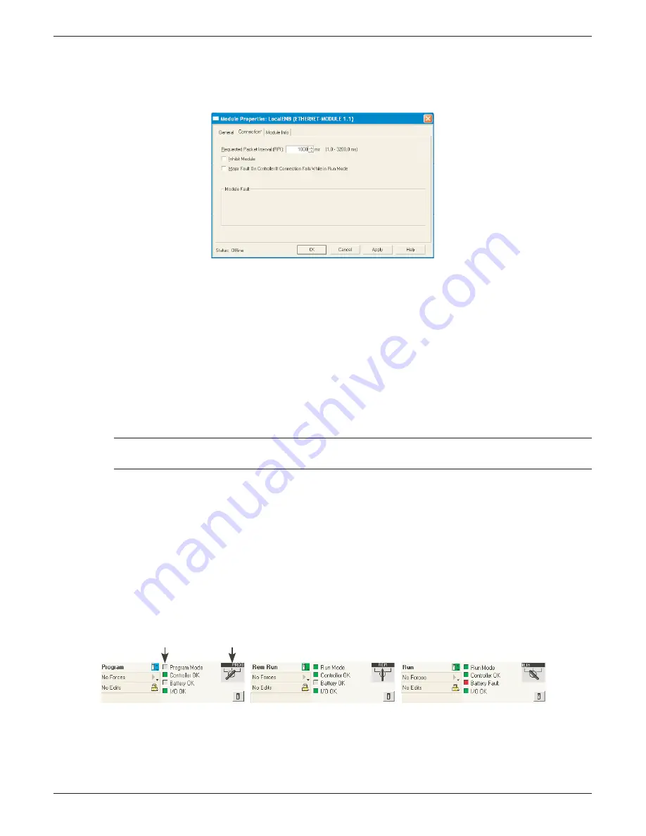
7. In the Module properties page (Figure 4.3.21q), set RPI to 1000 and click ‘OK’.
Figure 4.3.21q Module properties page
RECORDER CONFIGURATION
1. At the recorder. log in (
section 3.3.1
).
2. In the Operator/Confi g menu, touch the ‘Options’ item (at the bottom of the list). Check that ‘Ether-
Net/IP’ is enabled. If not, the software needs to be upgraded as described in
section 4.6.3
and an
‘Autoconfi gure’ carried out.
3. In the Operator/Confi g/Channels area (
section 4.3.3
), confi gure the channels as appropriate. Those
channels which are to receive data from the PLC should have their ‘Input Type’’ set to ‘EtherNet/IP
Comms Input’. The System/Copy facility (
section 4.6.8
) can be used to speed up the process. Maths
channels are set up is a similar way (
section 4.3.11
).
4. Set scale, units etc. to appropriate values.
Note... For the EtherNet/IP application, the number of decimal places is set to zero by default.
Editing this value may lead to loss of resolution in the values displayed.
5. Confi gure the EtherNet/IP input table as required (described earlier in this section).
7. Ensure that the PLC is connected to the recorder either directly using a cross-over EtherNet cable or
via a switch using non cross-over cable.
RUN MODE
1. Set the PLC into either ‘Remote’ or ‘Run’ mode.
2. Set the PLC online
STATUS INDICATORS
The status indicators at the top left corner of the RSLogix 5000 Page (Figure 4.3.21s) show the status of
the link between the pc and the PLC.
Figure 4.3.21s Status displays
It is possible to check that the PLC is communicating with the recorder using the ‘Tags’ display to write
values to the recorder and to receive values from it. Once it is proved that the link is working, the pc may
be disconnected from the PLC if required.
PLC Mode indicator
Status indicators


