【
4-25
】
SUSPENSION/STEERING/DRIVE SHAFT
●
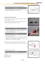
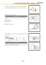
Fit a boot on the propeller shaft end, fitting the small diameter
side of the boot to the shaft groove, fix its end with a new band.
●
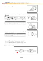
Install the cage [1] on the shaft.
[A] Large Diameter
[B] Small Diameter
●
Install the new snap ring.
●
Apply GREASE to the entire surface of the cage and the inside of
the outer race.
NOTE
The tube of joint grease is included in the wheel side boot set or
wheel side joint assembly of spare parts.
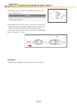
CAUTION
Install the cage with the large diameter side facing the shaft
end.
1
A
B
Outer
Inner
Quantity
45 g
85 g
Grease
Position
2
Содержание DL-702 2008
Страница 1: ...FOREWORD INDEX 0 0...
Страница 41: ...3 11 BRAKE...
Страница 180: ...6 70 ENGINE Install the starter motor...
Страница 201: ...7 21 COOLING AND LUBRICATION SYSTEM Engine Lubrication System Chart...
Страница 202: ...7 22 COOLING AND LUBRICATION SYSTEM Engine Lubrication System 1 2 3 1 2 3 1 2 3...
Страница 203: ...7 23 COOLING AND LUBRICATION SYSTEM 1 2 3...
Страница 205: ...7 2 ELECTRICAL SYSTEM Fuses 7 30 Main Fuse Removal 7 30 Fuse Inspection 7 30 Switches 7 31 Wiring Diagram 7 32...
Страница 235: ...7 32 ELECTRICAL SYSTEM Wiring Diagram...
Страница 236: ...7 33 ELECTRICAL SYSTEM Wiring Diagram...
Страница 237: ...7 34 7 34 ELECTRICAL SYSTEM ELECTRICAL SYSTEM...
Страница 238: ...7 35 ELECTRICAL SYSTEM NOTE...
Страница 240: ...9 2 PERIODIC MAINTENANCE...
Страница 246: ...9 8 PERIODIC MAINTENANCE Intake Side...
Страница 247: ...9 9 PERIODIC MAINTENANCE Exhaust Side Side...
Страница 270: ...9 32 PERIODIC MAINTENANCE 1 2 3 4 18 19 12 16 17 21 13 14 15 22 23 5 6 7 8 9 12 10 11 20...

