【
3-5
】
BRAKE
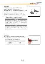
● Tighten
the bleed valve to the specified torque:
Tightening Torque: 5.5 N-m (0.55 kg-m, 4.0 lb-ft)
● Apply the brake lever forcefully for a few second, and check for
fluid leakage around the fittings.
Brake Line Air Bleeding
●
Bleed the air whenever brake parts are replaced or reassembled.
●
Remove the reservoir cap and fill the reservoir with new brake
fluid.
●
Slowly pump the brake lever several times until no air bubbles
can be seen rising up through the fluid from the hose at the
bottom of the reservoir. This bleeds the air from the master
cylinder and the brake line.
●
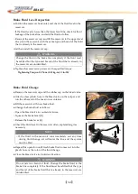
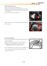
Attach a clear plastic hose to the bleed valve on the caliper, and
run the other end of the hose into a container.
●
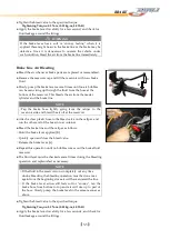
Bleed the brake line and the caliper as follows:
○
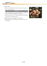
Hold the brake lever applied [B].
○
Quickly open and
close the bleed valve.
○
Release the brake lever [A].
● Repeat this operation until
no bubbles comes out the brake fluid
reservoir.
●
The fluid level must be checked several times during the bleeding
operation and replenished as necessary.
● Tighten
the bleed valve to the specified torque.
Tightening Torque: 5.5 N-m (0.55 kg-m, 4.0 lb-ft)
● Apply the brake lever forcefully for a few seconds, and check for
fluid leakage around the fittings.
A
B
NOTE
○
Tap the brake hose lightly going from the caliper to the
reservoir side and bleed the air off at the reservoir.
NOTE
○
If the fluid in the reservoir runs completely out any time
during bleeding, the bleeding operation must be done over
again from the beginning since air will have entered the line.
○
If the brake level action still feels soft or "spongy", tap the
brake hose from bottom to top and air will rise up to part of
the hose. Slowly pump the brake level in the same manner as
above.
WARNING
If the brake lever has a soft or "spongy feeling" when it is
applied, there might be air in the brake line or the brake may be
defective. Since it is dangerous to operate the vehicle under
such condition, bleed the air from the brake line immediately.
Содержание DL-702 2008
Страница 1: ...FOREWORD INDEX 0 0...
Страница 41: ...3 11 BRAKE...
Страница 180: ...6 70 ENGINE Install the starter motor...
Страница 201: ...7 21 COOLING AND LUBRICATION SYSTEM Engine Lubrication System Chart...
Страница 202: ...7 22 COOLING AND LUBRICATION SYSTEM Engine Lubrication System 1 2 3 1 2 3 1 2 3...
Страница 203: ...7 23 COOLING AND LUBRICATION SYSTEM 1 2 3...
Страница 205: ...7 2 ELECTRICAL SYSTEM Fuses 7 30 Main Fuse Removal 7 30 Fuse Inspection 7 30 Switches 7 31 Wiring Diagram 7 32...
Страница 235: ...7 32 ELECTRICAL SYSTEM Wiring Diagram...
Страница 236: ...7 33 ELECTRICAL SYSTEM Wiring Diagram...
Страница 237: ...7 34 7 34 ELECTRICAL SYSTEM ELECTRICAL SYSTEM...
Страница 238: ...7 35 ELECTRICAL SYSTEM NOTE...
Страница 240: ...9 2 PERIODIC MAINTENANCE...
Страница 246: ...9 8 PERIODIC MAINTENANCE Intake Side...
Страница 247: ...9 9 PERIODIC MAINTENANCE Exhaust Side Side...
Страница 270: ...9 32 PERIODIC MAINTENANCE 1 2 3 4 18 19 12 16 17 21 13 14 15 22 23 5 6 7 8 9 12 10 11 20...

