background image

ENGINE   


6-9


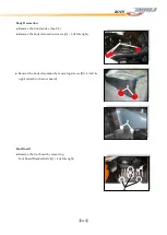
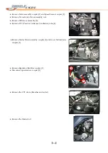
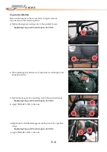
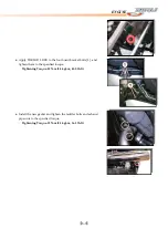
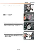
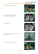
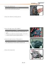
● 

Apply


THREAD


LOCK


to


the


foot


board


bracket


bolts


[1]


,


and


tighten


them


to


the


specified


torque.


Tightening


Torque:


55N

m


(5.5


kgf

m,


40.0


lb

ft)


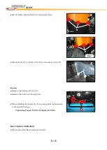
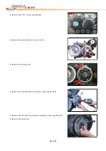
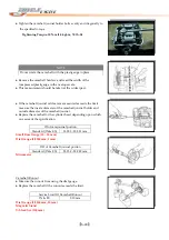
● 

Install


the


new


gasket


and


tighten


the


muffler


bolts


and


exhaust


pipe


nuts


to


the


specified


torque.


Tightening


Torque:


23N

m


(2.3


kgf

m,


16.5


lb

ft)


Содержание DL-702 2008

Страница 1: ...FOREWORD INDEX 0 0...

Страница 2: ...been taken to make it as complete and accurate as possible The right is reserved to make changes at any time without prior notice and without incurring an obligation to make such changes to products m...

Страница 3: ...and non scheduled maintenance Use proper tools and genuine DINLI vehicle parts Genuine parts provided as spare parts are listed in the Parts Catalog Follow the procedures in this manual carefully Don...

Страница 4: ...result in damage to or destruction of equipment This manual contains four more symbols in addition to WARNING and CAUTION which will help you distinguish different types of information NOTE This note...

Страница 5: ...RAL INFORMATION CHAPTER 2 WHEELS TIRES CHAPTER 3 BRAKE CHAPTER 4 SUSPENSION STEERING DRIVE SHAFT CHAPTER 5 BODY CHAPTER 6 ENGINE CHAPTER 7 COOLING AND LUBRICATION SYSTEM CHAPTER 8 ELECTRICAL SYSTEM CH...

Страница 6: ...tion 1 8 Fuel For USA and Canada 1 8 Fuel For Other Countries 1 8 Engine Oil For USA 1 8 Engine Oil For Other Countries 1 8 Front Differential Gear Oil 1 8 Rear Gear Final Box Oil 1 8 Brake Fluid 1 9...

Страница 7: ...t the positive wire to the positive terminal of the battery 3 Installation Assembly Generally installation or assembly is the reverse of removal or disassembly However if installation or assembly sequ...

Страница 8: ...revent oil or compression leaks 10 Liquid Gasket Locking Agent Clean and prepare surfaces where liquid gasket or non permanent locking agent will be used Apply them sparingly Excessive amount may bloc...

Страница 9: ...thermore necessary to rotate the engine in the direction of positive rotation as well 17 Replacement Parts When there is a replacement instruction replace these parts with new ones every time they are...

Страница 10: ...isconnect the negative cable first and then the positive cable When reconnecting the battery connect the positive cable first and then the negative cable and replace the terminal cover on the positive...

Страница 11: ...1 6 GENERAL INFORMATION DINLI DL 702 Right Side Left Side Difference between photograph and actual vehicle may exist depending on the markets...

Страница 12: ...ial number Vehicle identification number ENGINE SERIAL NUMBER Ex 15M18XXXXX VEHICLE IDENTIFICATION ex RFWAK85CX6Txxxxxx Whenever corresponding with DINLI about a particular issue the engine number and...

Страница 13: ...or SG under the API American Petroleum Institute service classification The recommended viscosity is SAE 10W 40 If SAE 10W 40 oil is not available select an alternative according to the following char...

Страница 14: ...an distilled water can corrode and clog the aluminum radiator Anti Freeze Engine Coolant The engine coolant performs as a corrosion and rust inhibitor as well as anti freeze Therefore the engine coola...

Страница 15: ...before subjecting the engine to maximum stresses The future performance and reliability of the engine depends on the care and restraint exercised during its early life The general rules are as follow...

Страница 16: ...re or during operating the ATV Maximum Vehicle Load 250kg 551 lbs Includes weight of operator cargo and accessories Never load over 250kg or may cause loss of control Always wear protective clothing w...

Страница 17: ...tem Liquid cooled 85 Cooling device operating temperature 1 2 water anti freeze ethylene glycol containing corrosion inhibitors for aluminum engines and radiators Coolant Starter system Electrical and...

Страница 18: ...n Transfer L H N R P Automatic transmission ratio Variable change 2 670 0 787 Secondary reduction ratio 2 158 40 21 17 15 Final reduction ratio Front Rear 3 600 36 10 Low 2 294 39 17 Transmission gear...

Страница 19: ...t DC 14V 23A 3000 rpm Battery GS GTX20L BS 12 V 20Ah Main fuse 30 A Fuse 5A 7 5A 10A 15A 30A Headlight 12V 35 35W Main 3W Position Taillight P21 5W RY 10W Indicator Speedometer LCD High beam indicator...

Страница 20: ...Wheel Rim 2 4 Removal 2 4 Installation 2 4 Inspection 2 5 Replacement 2 5 Tire 2 6 Removal 2 6 Installation 2 6 Inspection 2 8 Hub 2 9 Front Hub Removal 2 9 Front Hub Inspection 2 9 Front Hub Installa...

Страница 21: ...pressure when cold Front Rear Maximum tire bead seat pressure Front Rear Vehicle Maximum load capacity AT 25 8 12 MAXXIS M915 Tubeless AT 25 10 12 MAXXIS M916 Tubeless 35 kPa 0 35 kgf cm2 5 1 psi 35...

Страница 22: ...cs 11 Tire 2 Front Wheel Hub 7 Castle Nut 4pcs 12 Rim 3 Rear Wheel Hub 8 Cotter Pin 4pcs 13 Rim 4 FHSC 8pcs 9 Spring Washer 4pcs 14 Name Plate 4pcs 5 Insert Bolt 16pcs 10 Tire 15 Rim Valve 4pcs Item N...

Страница 23: ...he wheel Installation A A A Check the tire rotation mark A on the tire and install the wheel accordingly NOTE The direction of the tire rotation is shown by an arrow on the tire sidewall B Position th...

Страница 24: ...im see Tire Removal Remove the air valve and discard it CAUTION Replace the air valve whenever the tire is replaced Do not reuse the air valve 2 5 Install a new air valve in the new rim Remove the val...

Страница 25: ...allation Inspect the rim see Wheel Rim Inspection Replace the air valve with a new one Check the tire for wear and damage see Tire Inspection CAUTION When using the tire bead breaker do not scratch or...

Страница 26: ...the tire until the tire beads seat on the rim WARNING Do not inflate the tire to more than the maximum tire air pressure Over inflation can explode the tire with possibility of injury and loss of line...

Страница 27: ...ore operation Tire Inspection Examine the tire for damage and wear If the tire is cut or cracked replace it Lumps or high spots on the tread or sidewalls indicate internal damage requiring tire replac...

Страница 28: ...the caliper hang free Remove the axle nut and pull off the front hub with brake disc CAUTION Replace the removed cotter pin with a new one A B Separate the brake disc by removing the brake disc mount...

Страница 29: ...hten the axle nut to the specified torque Tightening Torque 110 N m 11 0 kgf m 79 5 lb ft Insert the new cotter pin and bent it over the nut Rear Hub Removal Remove the wheel See wheel Removal Remove...

Страница 30: ...ar hub in the reverse order of removal Pay attention to the following points Apply GREASE to the hub spline Tighten the axle nut 1 to the specified torque Tightening Torque 110 N m 11 0 kgf m 79 5 lb...

Страница 31: ...liper Installation 3 9 Caliper Inspection 3 10 Brake Pad 3 12 Removal 3 12 Installation 3 13 Inspection 3 13 Brake Disc 3 14 Disc Cleaning 3 14 Front Disc Removal 3 14 Rear Disc Removal 3 15 Front Dis...

Страница 32: ...ter Cylinder Assy 19 Pin 32 Braking Hose 7 Protector 20 Spring Washer 2pcs 33 Braking Hose 8 Hex Socket Bolt 4pcs 21 Washer 17pcs 34 Braking Hose 9 Hexagonal Flange Bolt 7pcs 22 Spring Washer 4pcs 35...

Страница 33: ...te will cause deterioration of the rubber parts Oil spilled on any parts will be difficult to wash off completely and will eventually deteriorate the rubber used in the disc brake 7 When handing the d...

Страница 34: ...container Fill the reservoir with new brake fluid Change the brake fluid as follows Open the bleed valve in counterclockwise Squeeze the brake lever B Release the brake lever A Check the fluid level...

Страница 35: ...out the brake fluid reservoir The fluid level must be checked several times during the bleeding operation and replenished as necessary Tighten the bleed valve to the specified torque Tightening Torque...

Страница 36: ...linder to catch any split fluid Remove the brake hose union bolt and disconnect the brake hose B Remove the master cylinder by taking off its clamp bolts A Remove the brake lever 1 CAUTION Brake fluid...

Страница 37: ...rque 9 N m 0 90 kg m 6 5 lb ft Use a new flat washer on each side of the brake hose fitting and tighten the banjo bolt Tightening Torque 25N m 2 5kg m 18 0 lb ft Bleed the brake line after master cyli...

Страница 38: ...moval Remove the rear wheel see Wheels Tires chapter Loosen the banjo bolt at the brake hose lower end and tighten it loosely Remove the caliper mounting bolts and detach the caliper from the disc Rem...

Страница 39: ...he reverse order of removal Pay attention to the following points Replace the washers 1 that are on each side of hose fitting with new ones Tighten the caliper mounting bolts 2 and the brake hose banj...

Страница 40: ...o the rear hub and tighten them to the specified torque Tightening Torque 25 N m 2 5 kgf m 18 0 lb ft Replace the circlips 1 with new ones Tighten the wire rope bolt 2 Caliper Inspection Inspect the b...

Страница 41: ...3 11 BRAKE...

Страница 42: ...e B remove the pads C Remove the anti rattle spring Rear Brake Remove the rear caliper See Caliper Removal Push the plate A remove the pads B Remove the anti rattle spring Parking Brake Remove the rea...

Страница 43: ...thickness A of the pads in each caliper If the lining thickness of either pad is less than the service limit B replace both pads in the caliper as a set WARNING Do not attempt to drive the vehicle un...

Страница 44: ...ront Brake Disc Removal Remove the front wheel see Wheel Removal Remove the front brake caliper Remove the front hub by removing its cotter pin and axle nut Remove the brake disc mounting bolts A Remo...

Страница 45: ...x bolts and slide the gear box backward Remove the disc Front Disc Installation The disc must be installed with the marked side A facing toward the steering knuckle Apply non permanent locking agent D...

Страница 46: ...point solvent Inspection Disc Wear Measure the thickness of each disc at the point A where it has worn the most Replace the disc if has worn past the service limit B Measuring Area Micrometer 0 25 mm...

Страница 47: ...Brake Hose Pump the brake fluid out of the line as explained in the Brake Fluid Change Remove the banjo bolts at both ends of the brake hose and pull the hose off the vehicle Immediately wipe up any...

Страница 48: ...sure valve by installing the brake hose banjo bolts and pressure valve mounting bolts Bleed the brake line see Brake Line Air Bleeding Check the brake for good braking power no brake drag and no fluid...

Страница 49: ...the brake pedal free play A Depress the brake pedal lightly by hand until the brake is applied If the free play is incorrect adjust it Brake Pedal Position Adjustment Remove the brake pedal see Brake...

Страница 50: ...he Removal steps to install the brake pedal Master Cylinder Removal Remove the master cylinder joint A and the banjo bolt B at the brake hose lower end and tighten it loosely Remove the brake hose C L...

Страница 51: ...d level A in the brake reservoir Bleed the brake line after master cylinder installation see Brake Line Air Bleeding Check the brake for good braking power and no fluid leakage WARNING Do not attempt...

Страница 52: ...izer Removal 4 18 Rear Stabilizer Installation 4 19 Front Propeller Shaft 4 20 Removal and Disassembly 4 20 Inspection and Reassembly 4 21 Installation 4 23 Rear Propeller Shaft 4 24 Removal 4 24 Insp...

Страница 53: ...3 Spring washer 2pcs 4 Driver shaft protector 14 Cap 2pcs 24 Spacer 2pcs 5 Front shock absorber 15 Hex socket bolt 2pcs 25 Spacer 6 Lower A arm 16 Hex washer face bolt 5pcs 26 C type circlip 7 Upper A...

Страница 54: ...nt wheel hubs with brake discs See brake chapter Remove the front brake calipers and hang it free Remove the driver shaft protector Remove the cotter pins and tie rod end nuts Remove the front brake d...

Страница 55: ...sorber lower mounting bolts nuts and the upper A arm washer face bolts nuts Remove the upper A arms 1 Remove the lower A arm washer face bolts nuts Remove the lower A arms 2 Remove the shock absorber...

Страница 56: ...s for wear or damage If any damages are found replace it with a new one Remove the snap ring 1 Remove the knuckle ends with the special tools Bearing Installer Set Front Fork Installer Hammer A arm In...

Страница 57: ...w one Bushing Inspect the rubber bushings A arm for wear or other damage If any damages are found replace them with new ones Oil Seal Inspect the Oil seal lips for wear or damage If any damages are fo...

Страница 58: ...y are in the steering knuckles Rotate the inner races by hand to inspect for abnormal noise and smooth rotation If there is anything unusual replace the bearing with a new one Remove the circlip Remov...

Страница 59: ...and disassembly Pay attention to the following points Install the hub bearings with the special tool Install the steering knuckle oil seal with the special tool The oil seal which has faces to the fr...

Страница 60: ...lb ft Lower 60 N m 6 0 kgf m 43 5 lb ft Tighten the shock absorber mounting lower bolt nut 1 to the specified torque Tightening Torque 60 N m 6 0 kgf m 43 5 lb ft Tighten the shock absorber mounting u...

Страница 61: ...ll the front brake calipers Install the front wheels tires Spring Pre Load Adjustment After installing the front shock absorbers adjust the spring pre load The spring adjusting sleeve on shock absorbe...

Страница 62: ...x washer face bolt 21 Spacer 2pcs 4 Driver shaft protector 13 Hex washer face bolt 2pcs 22 Spacer 5 Rear shock absorber 14 Hex washer face bolt 23 C type circlip 6 Double row angular bearing 15 Hex wa...

Страница 63: ...the driver shaft protector Remove the cotter pin and rear hub nut Remove the rear wheel hub Remove the rear stabilizer joint lower bolt nut Remove the rear shock absorber Remove the rear knuckle moun...

Страница 64: ...her face bolt nuts Inspection and Disassembly Rear Shock Absorber Inspect the shock absorber for oil leakage or damage If any damages are found replace the rear shock absorber with a new one Bushing I...

Страница 65: ...nuckle oil seal with a suitable bar Hub Bearing Inspect the inner race play of the hub bearing by hand while it is in the rear knuckle Rotate the inner race by hand to inspect for abnormal noise and s...

Страница 66: ...ion Reassemble and install the rear suspension in the reverse order of removal and disassembly Pay attention to the following points Apply GREASE to the hub bearings and the lips of the oil seals befo...

Страница 67: ...ghten rear knuckle bolt nut to the specified torque Tightening Torque 60 N m 6 0 kgf m 43 5 lb ft Apply THREAD LOCK to the rear shock absorber mounting bolts and then tighten the nut to the specified...

Страница 68: ...bsorber has 5 positions so that the spring can be adjusted for different terrain and loading conditions If the spring action feels too soft or too stiff adjust it in accordance with the following phot...

Страница 69: ...ge If any damages are found replace the rear stabilizer bar with a new one Stabilizer Bracket Bushing Inspect the stabilizer bracket for damage If any damage are found replace the stabilizer bracket w...

Страница 70: ...SION STEERING DRIVE SHAFT Rear Stabilizer Installation Install the stabilizer bar Tighten the rear stabilizer bracket bolts Tighten the rear stabilizer joint bolt nut Tightening Torque 34 N m 3 4 kgf...

Страница 71: ...emove the boot bands of the differential side joint double offset joint Slide the boot toward the center of the front propeller shaft and remove the stopper ring from the outer race Separate the outer...

Страница 72: ...all the cage 1 on the shaft A Large Diameter B Small Diameter NOTE Wash the disassembled parts except for the boots After washing completely dry the parts using compressed air Clean the boots with a c...

Страница 73: ...iver into the boot on the outer race side and allow air to enter the boots so that the air pressure in the boot becomes the same as the atmospheric pressure at the positions indicated in the illustrat...

Страница 74: ...4 23 SUSPENSION STEERING DRIVE SHAFT Installation Install the front propeller shaft in the reverse order of removal...

Страница 75: ...ands for wear or damage If any damages are found replace them with new ones Inspect the axle play by using a push and pull motion given to the axle shaft and wheel spindle as shown NOTE Wash the disas...

Страница 76: ...he shaft A Large Diameter B Small Diameter Install the new snap ring Apply GREASE to the entire surface of the cage and the inside of the outer race NOTE The tube of joint grease is included in the wh...

Страница 77: ...the boot on the outer race side and allow air to enter the boot so that the air pressure in the boot becomes the same as the atmospheric pressure at the positions indicated in the illustration A 188 1...

Страница 78: ...ate 13 Cotter pin 2 Steering Tie rod assy 2sets 8 Bush bearing 14 Cotter pin 4pcs 3 Steering shaft bracket 2pcs 9 Oil seal 2pcs 15 Spring washer 4pcs 4 Pin 10 Hexagonal flange bolt 16 Washer 4pcs 5 Se...

Страница 79: ...ar clamp bolts Remove the wire rope that from the handlebar assembly See Handlebar Removal Remove the handlebar upper clamps A Remove the handlebar Remove the cotter pins and tie rod end nuts Separate...

Страница 80: ...et bolts Remove the steering shaft brackets spacers oil seals and plate Remove the steering shaft Remove the seal cover 1 pin 2 bush bearing 3 and washer 4 CAUTION Replace the removed oil seals with n...

Страница 81: ...m with new ones Tie Rod Inspect the tie rod for distortion or damage If any damages are found replace it with a new one Tie Rod End Inspect the tie rod ends and boots for smooth movement If there are...

Страница 82: ...ge If any damages are found replace it with new one Inspect the steering shaft seal cover for any scratches or other damage If any damages are found replace the shaft seal cover with new ones Inspect...

Страница 83: ...torque Tightening Torque 23 N m 2 3 kgf m 16 5 lb ft Install the steering shaft lower nut with the washer Tighten the steering shaft lower nut to the specified torque Tightening Torque 120 N m 12 0kgf...

Страница 84: ...clamp align the brake reservoir on the horizontal direction of the handlebar Install the handlebar upper clamps as shown First tighten the bolts 1 to the specified torque and then tighten the bolts 2...

Страница 85: ...t until the toe out is within the specified range B A Tie out Temporarily tighten the four locknuts Check that the distance C and D are equal as shown If the distances are not equal adjust the tie rod...

Страница 86: ...ndlebar 6 Handle grip 2pcs 11 Right lever assy 2 Throttle wire 7 Hex socket bolt 4pcs 12 Left lever assy 3 Choke cable 8 Rear View mirror L 13 Right switch 4 Upper handlebar clamp L 9 Rear View mirror...

Страница 87: ...ove the brake hose Remove the brake master cylinder assembly See Brake chapter Remove the throttle wire Remove the right switch assembly Remove the choke cable by removing its cap 1 Remove the parking...

Страница 88: ...hat the angle of the handlebar matches the angle of the steering stem as shown Install the handlebar upper clamps as shown First tighten the bolts 1 to the specified torque and then tighten the bolts...

Страница 89: ...ator T M level 18 Level assy rod 3 Indicator T M level 11 Indicator T M level bracket 19 Tie rod end 2pcs 4 T M level cover 12 Spacer 2pcs 20 Level rod 5 Tapping screw 4pcs 13 Washer 3pcs 21 Nut 6 Hex...

Страница 90: ...SION STEERING DRIVE SHAFT Removal Remove the indicator T M lever knob 1 indicator level tapping screws 2 and mounting bolts 3 Loosen the bolt 1 and remove the tie rod end 2 Remove the T M lever assemb...

Страница 91: ...eplace it with a new one Installation Install the indicator T M lever in the reverse order of removal Pay attention to the following points Apply GREASE to level shaft Install the T M lever assembly t...

Страница 92: ...ly keep the tie rod end 1 in the N position Install the tie rod end 1 on its shaft Tighten the bolt 2 securely NOTE When installing the tie rod end align the tie rod end s grooves with the spline of t...

Страница 93: ...If the lever can not move successfully measure the tie rod length and adjust the tie rod to the proper position Adjust the tie rod in two positions as shown in the figure CAUTION Adjust the tie rod le...

Страница 94: ...tion 5 4 Front and Rear Fenders 5 5 Front Fender Construction 5 5 Front Fender Removal 5 6 Front Fender Installation 5 10 Rear Fender Construction 5 11 Rear Fender Removal 5 12 Rear Fender Installatio...

Страница 95: ...se to seat open position B Lift the seat front slightly pull it toward the front and remove the seat Seat Installation Align the catch A at the back of the seat with the receiver B on the frame Slip t...

Страница 96: ...Front and Rear Racks Front and Rear Racks Removal Remove the front rack by removing its bolts A 4 left right B 2 left right Remove the rear rack by removing its bolts C 2 left right D 2 E 2 left right...

Страница 97: ...5 4 BODY Front and Rear Racks Installation Install the front and rear rack in the reverse order of removal NOTE When installing the racks notice that the difference between front and rear rack...

Страница 98: ...partment 12 Hook cover 21 Plug 4 Front fender L 13 Clip nut 10pcs 22 Fixed plate 4pcs 5 Front fender R 14 Hex washer face bolt 23 Fixed plate 2pcs 6 Front fender under cover 15 Hex washer face bolt 2p...

Страница 99: ...fender decoration B by inserting the opening stick into the hole A to open it Remove the maintenance compartment C by removing its screws and bolts D 4 left right attach to the front fender E 2 left...

Страница 100: ...move the front fender decoration See 5 6 Remove the headlight lead wire coupler A Remove headlight shade by unscrew the screws B 5 C 6 left right attach to the front fender Front Fender Under Cover Re...

Страница 101: ...B 4 Front Fender Left Right Remove the front rack See 5 3 Remove the maintenance compartment See 5 6 Remove the headlight shade See 5 7 Remove Left and Right Fender by removing A 6 left right attach...

Страница 102: ...the fuel tank cap B Remove the fuel tank decoration by removing its bolts attach to the luggage compartment Fuel Tank Remove the fuel tank decoration See 5 9 Disconnect the Fuel level indicator lead w...

Страница 103: ...5 10 BODY Remove the fuel tank by removing its bolts Front Fender Installation Please reverse the Removal steps to install...

Страница 104: ...2pcs 3 Left body decoration 11 Screw 6pcs 19 Heat insulation pad 4 Right body decoration 12 Pan head bolt 4pcs 20 Hex washer face bolt 2pcs 5 Rear fender 13 Machine screw 16pcs 21 Tapping screw 2pcs 6...

Страница 105: ...Remove the seat See 5 2 and rear rack See 5 3 Remove the taillight lead wire coupler left right Remove the rear fender by removing A 6 attach to luggage compartment B 3 attach to luggage compartment C...

Страница 106: ...fender See 5 8 Remove the body decoration screws A 6 left right Remove the body decoration by removing screws B 4 left right attach to the foot board Foot Board Remove the foot board by removing Foot...

Страница 107: ...ee 5 13 Footrest Remove the footboard See 5 13 Remove the footrest mounting bolts When installing the footrest by its mounting bolts tighten them to the specified torque Tightening Torque 55 N m 5 5 k...

Страница 108: ...olts Remove the battery Remove the electrical relays and units Remove the fuel tank decoration See 5 9 Remove the seat hook wire rope See 5 9 Remove the rear fender See 5 12 Remove the intake pipe cla...

Страница 109: ...5 16 BODY Drainage Plug Inspection Check the drainage plug and the compartments for accumulating water If the water had been accumulated drain the water and clean the compartments...

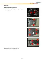
Страница 110: ...5 17 BODY Protector Protector Removal Installation Remove the front 1 engine 2 and rear protector 3 by removing its bolts Install the protector by installing their bolts 1 1 2 3...

Страница 111: ...ction 6 23 Camshaft and Cylinder Head 6 23 Cam Chain Tensioner 6 32 Cam Chain Guide 6 32 Cylinder 6 32 Timing Gear 6 34 Piston 6 35 Connecting Rod 6 37 Clutch 6 38 Oil Gallery Copper Plug 6 39 Movable...

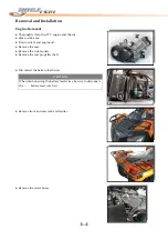
Страница 112: ...rk area Drain coolant and engine oil Remove the seat Remove the side fenders Remove the rear propeller shaft Disconnect the battery lead wires CAUTION When disconnecting the battery lead wires be sure...

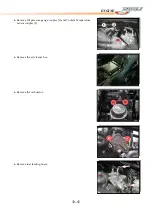
Страница 113: ...ENGINE 6 3 Remove Oil pressure gauge coupler 1 and Coolant Temperature sensor coupler 2 Remove the air cleaner box Remove the carburetor Remove fuel feeding hoses...

Страница 114: ...embly rod Remove Shift lever assembly 3 Remove PCV Positive Crankcase Ventilation tube 4 Remove Starter Motor assembly coupler 1 and Gear shift indicator coupler 2 Remove Regulator Rectifier coupler 1...

Страница 115: ...move the high voltage cable Remove the Exhaust pipe bolts Remove the muffler Remove the right foot board Remove the right foot board bracket bolts 1 Remove the right foot board bracket Remove the foot...

Страница 116: ...NGINE Remove the front differential mounting bolts nuts Slide the front differential assy forward Remove the front propeller shaft spring Remove the front propeller shaft Remove the rear gear box bolt...

Страница 117: ...ENGINE 6 7 Slide the rear gear box assy backward Remove the rear propeller shaft spring Remove the rear propeller shaft Remove the engine mounting bolts nuts Remove the engine from the right side...

Страница 118: ...60N m 6 0 kgf m 43 5 lb ft When installing the shift lever rod adjust the tie rod length to the properly position Tighten the rear gear box mounting nuts to the specified torque Tightening Torque 50N...

Страница 119: ...bracket bolts 1 and tighten them to the specified torque Tightening Torque 55N m 5 5 kgf m 40 0 lb ft Install the new gasket and tighten the muffler bolts and exhaust pipe nuts to the specified torqu...

Страница 120: ...6 10 ENGINE Engine Disassembly Engine Top Side Remove the spark plug Remove the start motor Remove water hoses 1 and 2 Remove the water union Remove the recoil starter...

Страница 121: ...the crankcase B A A B NOTE At the above condition the piston is at TDC of compression stroke and also the engraved marks C on the camshafts are parallel with the mating surface of the cylinder head c...

Страница 122: ...e the cam driver gear 1 by removing the shaft cover 2 shaft 3 and the spacer 4 3 2 1 NOTE Be careful not to drop the spacer 4 into the crankcase Remove the cylinder head bolts M6 1 Remove the cylinder...

Страница 123: ...the cylinder nuts 4 Remove the cylinder 5 Remove the dowel pins 1 and the gasket 2 NOTE Be careful not to drop the dowel pins into the crankcase Remove the piston by removing the piston pin circlip 1...

Страница 124: ...m Side Remove the oil filter with the special tool Remove the water pump cover 1 Remove the starter cup nut with a suitable bar 1 Remove the starter cup 2 Remove the left crankcase cover 3 Remove the...

Страница 125: ...Remove the gearshift shaft 1 Remove the gearshift cam driven gear 2 by removing its bolts Remove the generator rotor bolt Rotor Mounting Socket Wrench Install the special tool to the crankshaft end D0...

Страница 126: ...the balancer shaft driven gear bolts with the special tool Stopper Plate Remove the oil pump driven gear CAUTION The oil pump drive gear and the oil pump driven gear must removed at the same time Rem...

Страница 127: ...and the oil pump Remove the balancer shaft driven gears 1 1 2 Remove the water pump drive gear 2 Remove the keys 1 1 Remove the cam chain drive gear with the special tools Bearing Remover Set Remove...

Страница 128: ...he CVT cover 1 and gasket Remove the movable drive face cover 1 Remove the dowel pins Remove the movable drive face 2 by removing the bolt Remove the movable driven face assembly by removing the bolt...

Страница 129: ...rear output connectors Remove the plate 1 CVT inner cover 2 and gasket Remove the gear position indicator 1 Remove the pin Remove the clutch housing shaft 1 NOTE Be careful about the size of the bolts...

Страница 130: ...6 20 ENGINE Remove the output shaft 2 Remove the collar 1 Remove the drive bevel gear 2 Remove the dowel pins 1 Remove the O ring Remove the one way clutch...

Страница 131: ...right crankcase bolts M6 M8 NOTE Loosen the crankcase bolts diagonally with the smaller sizes first Separate the right crankcase with the special tool Remove the dowel pins 2 There have two more bolt...

Страница 132: ...cam drum 5 Remove the seminal gear 6 Remove the countershaft assembly 7 Remove the input main shaft 8 Remove the final shaft T M assembly 9 CAUTION Do not attempt to disassemble the output driven gear...

Страница 133: ...rating smoothly If it does not operate smoothly or the spring occur elastic fatigue replace the camshaft automatic decompression assembly with a new one Camheight Check for damage and wear on cam prof...

Страница 134: ...he limit measure the inside diameter of the camshaft journal holder and outside diameter of the camshaft journal Replace the camshaft or the cylinder head depending upon which one exceeds the specific...

Страница 135: ...he valve 3 from the combustion chamber side Remove oil seals 1 and spring seats 2 NOTE Do not reuse the removed oil seals Cylinder head distortion Clean and remove carbon deposits from the surface Nev...

Страница 136: ...al gauge at right angles to the valve head face and measure the valve head radial runout If it measures more than the limit replace the valve Service Limit Of Valve head radial runout IN EX 0 03 mm Di...

Страница 137: ...e the guide Measure OD of Valve Stem sliding portion at total 6 points upper middle and lower positions and X and Y directions by means of micrometer Service Limit of Valve Guide OD IN 5 450 5 465 mm...

Страница 138: ...prevent the possibility of the tappet shim replacement If the contact area is too high on the valve or if it is too wide use the 30 60 cutters to lower and narrow the contact area If the contact area...

Страница 139: ...assemble the head and valve components Use the vacuum pump gauge to cover intake and exhaust ports and check for leaks If any leaks occur inspect the valve seat and face for burrs or other things that...

Страница 140: ...e lip of the oil seal Install the valve spring with the small pitch portion 1 facing cylinder head 2 Large pitch portion 3 Upward 3 1 2 Install the valve spring and spring retainer with special tool C...

Страница 141: ...the camshaft If the value is not correct use the tappets 1 to adjust the valve clearance Valve Clearance IN 0 1 0 2 mm EX 0 2 0 3 mm Thickness Gauge 1 Intake Pipe Remove the intake pipe 1 Apply GREAS...

Страница 142: ...READ LOCK to the thread part of water bypass union and tighten it to the specified torque Tightening Torque 14 N m 1 4 kgf m 10 0 lb ft Thermostat Remove the thermostat cover 1 Remove the thermostat C...

Страница 143: ...g at every position of the straightedge exceeds the limit replace the cylinder Cylinder Distortion Service Limit 0 05 mm Thickness Gauge Recognize Cylinder Different color on the cover of outside cyli...

Страница 144: ...the TDC line A with the index mark B of the crankcase to make the piston to the highest position A B B A Make the mark C on the Timing chain driver gear to the highest position Meanwhile the mark on t...

Страница 145: ...linder B Piston has to be matched with B cylinder Piston Rings Clearance between Piston Ring and groove Measure the clearance between Piston Ring and groove by holding the Ring upwards in the groove w...

Страница 146: ...ervice Limit of Piston Ring end gap Top ring 0 50 mm Second ring 0 50 mm Thickness Gauge Piston pin and pin bore ID of Piston hole for Pin Clean Piston hole for Pin Measure ID in the up and down direc...

Страница 147: ...e rod This method can also check the extent of wear on the rod s big end Connecting Rod deflection Service Limit 0 3 mm Magnetic Stand Dial Gauge 1 100 mm V block Set 100 mm Side clearance at large en...

Страница 148: ...wear If any damages are found replace the clutch wheel with a new one Starter Clutch Remove the starter clutch securing bolts Install the starter clutch in the proper direction Apply the engine oil to...

Страница 149: ...turns in the direction of the arrow If there is anything unusual replace the one way clutch Check the starter driven gear bearing If there is anything unusual replacing the bearing Remove the bearing...

Страница 150: ...l seal 2pcs 13 Movable drive plate 23 Spring 4 Hexagonal flange bolt 14 Movable drive face 24 Pin 4pcs 5 Hexagonal flange bolt 15 Roller set 8pcs 25 Ring 4pcs 6 Hexagonal flange bolt 16 Slide piece 4p...

Страница 151: ...and sliding surface Inspect each roller and their sliding surface for wear or damage If any damages are found replace the rollers as a set Front Side NOTE The rollers must always be changed as a set O...

Страница 152: ...ed drive face in the reverse order of disassembly Apply a small amount of GREASE to the bore and oil seal lip CAUTION Wipe off any excess grease thoroughly Take care not to apply grease to the contact...

Страница 153: ...ING Do not remove the movable driven face ring nut before attaching the clutch spring compressor Ring Nut Socket Wrench Attach the special tool to the movable driven face assembly and compress the mov...

Страница 154: ...ove the movable driven face O ring and Oil seal Inspect the lip of the oil seal and O ring for wear or damage If any damages are found replace the oil seal or O ring with a new one Remove the oil seal...

Страница 155: ...fixed driven face Inspect the driven faces for any abnormal conditions such as stepped wear or discoloration caused by burning If any damages are found replace the movable driven face with a new one...

Страница 156: ...ith the holes Compress the spring with the special tool Tighten the movable driven face ring nut temporarily Remove the special tool from the movable driven face assembly Tighten the movable driven fa...

Страница 157: ...surement exceeds the service limit replace the drive belt with a new one Drive belt width Service Limit 33 3 mm CAUTION If grease or oil is present on the surface of the drive belt degrease the belt t...

Страница 158: ...er shaft 05 Hex washer bolt 17 Indicator switch 29 Fork 41 Low driven gear 06 Flange hex nut 18 Dowel pin 30 Pin 2pcs 42 Reverse driven gear 07 Spacer 19 Output shaft 31 Fork 2pcs 43 High T M gear 08...

Страница 159: ...g After a snap ring has been removed from a shaft it should be discarded and a new snap ring must be installed When installing a new snap ring do not expand the end gap larger than required to slip th...

Страница 160: ...to groove clearance by using the thickness gauge If the clearance exceeds the limits replace the fork or its gear or both Shift for to groove clearance Standard 0 10 0 27 mm Service Limit 0 50 mm Thic...

Страница 161: ...ll the water pump and its cover See Water Pump Reassembly and Installation Reassembly Install the oil seals with the special tool necessary CAUTION It is necessary to put the oil seals and needle bear...

Страница 162: ...6 52 ENGINE Install the bearings with the special tool Install the generator stator assy CAUTION The harness of the sensor must be fastened to prevent for hitting the stator...

Страница 163: ...face and driven face away from any greasy matter Engine Bottom Side Install the crankshaft into crankcase CAUTION Never fit the crankshaft into the crankcase by striking it with a plastic mallet Inst...

Страница 164: ...se NOTE Fit the thinner side of the oil sump filter in the bottom as shown Tighten the crankcase bolts a little at a time to equalize the pressure until the specified torque Tightening torque M6 10 N...

Страница 165: ...o the specified torque Tightening Torque 150 N m 15 0 kgf m 108 5 lb ft NOTE The clutch shoe nut has left hand threads Apply MOLYBDENUM OIL to the inside of the one way clutch Install the one way clut...

Страница 166: ...cleaning solvent to wipe off oily or greasy matter and make its surfaces completely dry CAUTION Movable Driven Face Spring Compressor The other way is using the same size bolts which at least 70 mm l...

Страница 167: ...ve face assembly Use nonflammable cleaning solvent to wipe off oily and greasy matter and make its surfaces completely dry NOTE Be careful about the direction of the collar Tighten the movable drive f...

Страница 168: ...n the clutch cover bolts to the specified torque Tightening Torque 9 N m 0 9 kgf m 6 5 lb ft Install the pin Install the balancer shaft drive gear Install the cam chain drive gear with the special too...

Страница 169: ...to the direction of the water pump drive gear and oil pump drive gear Apply THREAD LOCK to the oil pump mounting bolts Install the pin 1 Install the oil pump drive gear 1 and oil pump driven gear with...

Страница 170: ...am chain guide Tighten the cam chain guide bolt to the specified torque Tightening Torque 23 N m 2 3 kgf m 16 5 lb ft Install the starter driven gear 1 Install the key 2 NOTE Degrease the tapered port...

Страница 171: ...ightening Torque 160 N m 16 0 kgf m 115 lb ft Install the gearshift cam stopper the stopper 1 bolts 2 and return spring 3 Install the gearshift cam stopper 1 and cam driven gear 2 NOTE Hook the return...

Страница 172: ...starter reduction gear and gearshift shaft Install the dowel pins 1 and new gasket 2 2 1 Install the copper plug and its O ring Install the generator cover 1 Install the starter cup NOTE Fit the pin...

Страница 173: ...oil filter with the special tool D003 Oil Filter Wrench Engine Top Side Install the piston rings in the order of oil ring second ring and first ring The first member to go into the oil ring groove is...

Страница 174: ...Install the piston and piston pin Place a clean rag over the crankcase Install the circlip Fit the dowel pins 1 and the new gasket 2 Piston 3 has to be matched with same level cylinder see 6 35 and 6...

Страница 175: ...nd cam drive sprocket Install the cam chain guide 1 Fit the dowel pins 2 and new cylinder head gasket 3 2 1 CAUTION Use a new gasket to prevent gas leakage 3 Install the cylinder head Tighten the cyli...

Страница 176: ...Install the cam drive idle gear sprocket with cam drive chain onto the cylinder head Align the punched mark on the cam drive idle gear sprocket with the embossed line on the cylinder head Install the...

Страница 177: ...ied torque Tightening Torque 10 N m 1 0 kgf m 7 0 lb ft Install the new O ring Install the cam chain tensioner cap bolt Tighten the cam chain tensioner cap bolt to the specified torque Tightening Torq...

Страница 178: ...M OIL SOLUTION to the camshaft journal holders NOTE Before installing the camshaft check that the tappets are installed correctly Tighten the camshaft journal holder bolts to the specified torque Tigh...

Страница 179: ...lb ft Final 14 N m 1 4 kgf m 10 0 lb ft NOTE Apply engine oil to the both side of head cover washer before installing the head cover bolts Tighten the valve timing inspection plug to the specified tor...

Страница 180: ...6 70 ENGINE Install the starter motor...

Страница 181: ...r Hose Inspection 7 7 Cooling Fan 7 8 Inspection 7 8 Removal 7 8 Remounting 7 8 Cooling Fan Thermo Switch 7 9 Removal 7 9 Inspection 7 9 Installation 7 9 ECT Sensor 7 10 Removal 7 10 Inspection 7 10 I...

Страница 182: ...er Do not mix an alcohol base anti freeze and different brands of anti freeze Do not use a radiator anti leak additive Anti freeze 1334 ml Water 666 ml WARNING You can be injured by scalding fluid or...

Страница 183: ...ds this pressure for 10 seconds If the pressure should fall during this 10 second interval it means that there is a leaking point in the system In such a case inspect the entire system and replace the...

Страница 184: ...lant by removing the drain plug Remove the right headlight Disconnect the cooling fan motor lead wire coupler 1 and cooling fan thermo switch leas wire coupler 2 Remove the front grill upper cover Dis...

Страница 185: ...his cleaning Remove the radiator fin guard net Fins bent down or dented can be repaired by straightening them with the blade of a small screwdriver Radiator Remounting Install the radiator in the reve...

Страница 186: ...adiator Cap Inspection Remove the radiator cap lid Fit the cap 1 to the radiator cap tester 2 Build up pressure slowly by operating the tester Make sure that the pressure build up stops at 110 140 kPa...

Страница 187: ...e the left headlight Remove the left inner fender Remove the left side cover Any radiator hose found in a cracked condition or flattened must be replaced Any leakage from the connecting section should...

Страница 188: ...electric motor fan running at full speed the ammeter 4 should be indicating not more than 5 3 amperes If the fan motor does not turn replace the cooling fan assembly with a new one Removal Remove the...

Страница 189: ...ater to raise its temperature slowly and read the column thermometer 2 when the switch closes or opens Multi circuit tester set Tester knob indication Continuity test Installation Install the new O ri...

Страница 190: ...its temperature slowly and read the column thermometer 3 and the ohmmeter If the ECT sensor ohmic value does not change in the proportion indicated replace it with a new one If the resistance is noted...

Страница 191: ...e ECT sensor in the reverse order of removal Tighten the ECT sensor to the specified torque Tightening Torque 20 N m 2 0 kgf m 14 44 lb ft Pour engine coolant CAUTION Take special care when handling t...

Страница 192: ...g manner Pass a string between flange immerse the thermostat in the water contained in a beaker as shown in the illustration Note that the immersed thermostat is in suspension Heat the water 1 by plac...

Страница 193: ...to open temperature and valve lift must be replaced Installation Install the thermostat in the reverse order of removal Apply engine coolant to the rubber seal on the thermostat After installing the...

Страница 194: ...the impeller shaft pin 3 and washer 4 NOTE Before draining engine coolant inspect engine coolant leakage between the water pump and crankcase If engine oil is leaking visually inspect the oil seal and...

Страница 195: ...remover set Place a rag over the water pump Remove the oil seal using a suitable bar Remove the needle bearing from the front side as shown Visually inspect the oil seal for damage with particular at...

Страница 196: ...he water pump in the reverse order of removal and disassembly Pay attention to the following points Install the needle bearing from the other side and make sure the mark is face to the engine Apply a...

Страница 197: ...Apply GREASE to the impeller shaft Install the impeller shaft and the impeller to the water pump body Install the washer 1 and impeller shaft pin 2 to the impeller shaft Install the water pump driven...

Страница 198: ...O ring 1 Install the water pump cover 1 and tighten its mounting bolts to the specified torque Tightening Torque 10 N m 1 0 kgf m 7 0 lb ft Connect the radiator hoses Pour engine coolant CAUTION Use...

Страница 199: ...oil to the gasket of the new oil filter before installation Install the new oil filter to the engine Turn it by hand until you feel that the oil filter gasket has contacted the oil filter mounting sur...

Страница 200: ...it moves smoothly If it does not move smoothly replace the oil pump assembly NOTE When installing the oil sump filter always use the new one to keep oil clean And the thinner side is face to the CVT C...

Страница 201: ...7 21 COOLING AND LUBRICATION SYSTEM Engine Lubrication System Chart...

Страница 202: ...7 22 COOLING AND LUBRICATION SYSTEM Engine Lubrication System 1 2 3 1 2 3 1 2 3...

Страница 203: ...7 23 COOLING AND LUBRICATION SYSTEM 1 2 3...

Страница 204: ...Spark Plug Removal Installation 7 17 Spark Plug Cleaning Inspection 7 17 Spark Plug Gap 7 18 Ignition Coil Removal 7 18 Ignition Coil Installation 7 18 Ignition Coil Inspection 7 18 CDI Output Test 7...

Страница 205: ...7 2 ELECTRICAL SYSTEM Fuses 7 30 Main Fuse Removal 7 30 Fuse Inspection 7 30 Switches 7 31 Wiring Diagram 7 32...

Страница 206: ...egulator rectifier output DC 14 15 V Alternator no load output voltage AC 65 V and more at 5000 rpm Y1 Y2 0 49 Charge Coil Stator Y2 Y3 0 49 Y3 Y1 0 49 Y Ground Pulser Coil Bu Y G W 110 15 Ignition Co...

Страница 207: ...E D A Battery G Ignition Coil B Starter Circuit Relay H Regulator Rectifier C CDI Unit I Gear Position Indicator D Flash Relay J Starter Motor E Position Light Relay K 2WD 4WD Diff 4WD Actuator F Tra...

Страница 208: ...H D A B H C A High Low Beam Switch G Ignition Switch B Hazard Lights Switch H Spark Plug C Horn Switch I Cooling Fan D Indicator Switch J Temperature Sensor E Diff 4WD Confirm Button K Speed Sensor F...

Страница 209: ...d wire first If the terminal is corroded remove the battery pour warm water over it and clean it with a wire brush After connecting the battery apply a light coat of grease to the battery terminals Al...

Страница 210: ...to drop the part with a semi conductor built in such as a CDI unit Properly use the multi circuit tester and probes Improper use can cause damage to the vehicle and tester If the voltage and current...

Страница 211: ...f the connector is corroded or dirty clean it carefully If it is damaged replace it Check the wiring for continuity Use the wiring diagram to find the ends of the lead which is suspected of being a pr...

Страница 212: ...intenance free design and construction Use of conventional lead acid batteries is not recommended No electrolyte or refilling water is required Because this battery is a completely sealed type abuse o...

Страница 213: ...ecified may ruin the battery Charging at a high rate causes excess heat which can warp the plates and cause internal shorting Higher than normal charging rates also cause the plates to shed active mat...

Страница 214: ...fully charged the trouble may be that there is not enough acid in that one cell In this case only sulfuric acid solution may be added to correct the specific gravity If a fully charged battery doesn t...

Страница 215: ...akage OK Step3 Measure the regulated voltage between the battery terminals Is the regulated voltage OK Step4 Measure the resistance of the alternator coil Is the resistance of alternator coil OK YES R...

Страница 216: ...on Battery Current Leakage Remove the seat Turn the ignition switch to the OFF position Disconnect the battery lead wire 1 Measure the current between battery terminal and the battery lead wire with t...

Страница 217: ...Battery 14 15 V Turn off the ignition switch to stop the engine and remove the seat Remove the battery stay 1 1 Measure the DC voltage between the and terminals with the multi circuit tester If the r...

Страница 218: ...on Resistance Alternator coil resistance 0 1 1 0 Y Y Y Grnd NOTE When making above test it is not necessary to remove the alternator Alternator no load performance Disconnect the alternator coupler 1...

Страница 219: ...ere electrical shock CAUTION Do not disconnect the battery leads or any other electrical connections when the ignition switch is on or while the engine is running This is to prevent CDI unit damage Do...

Страница 220: ...lug wrench from the vehicle right side When installing the spark plug make sure to tighten the spark plug to the specified torque Tightening Torque 14 N m 1 4 kgf m 10 0 lb ft Spark Plug Cleaning Insp...

Страница 221: ...ition coil Measure the primary winding resistance as follows Connect the tester between the coil terminals Set the tester to the 1 range and read the tester Measure the secondary winding resistance as...

Страница 222: ...lay coil resistance between the terminals with the multi circuit tester If the resistance is not within the specified value replace the starter relay with a new one Multi Circuit Tester Set Tester kno...

Страница 223: ...main relay 1 1 First check the insulation between 1 and 4 terminals with the tester Then apply 12 V to terminals 2 and 3 and check the continuity between 1 and 4 If there is no continuity replace the...

Страница 224: ...ng the transfer selecting switch The voltage must maintain at 12 V if the voltage does not conform to the standard check the continuity of each lead wire or replace the actuator assembly with a new on...

Страница 225: ...se compared to those currently in use because of this composition 1 5 2 6 3 4 7 8 13 9 10 11 14 12 Mode Button 1 8 Engine Oil Indicator Coolant Temperature Indicator 4WD Differential Lock Indicator 2...

Страница 226: ...sly 4 Setting Button Press button to switch the display of Clock Hour Tacho Temp Meter 5 Indicator Light When the indicator switch is operated this indicator light will blink and the buzzer will sound...

Страница 227: ...ur Tacho Temp Meter This display has four functions Clock Hour Tacho and Temp meter To change the display press Set button shortly Clock Display the time in 12 hour To set the clock change to Clock mo...

Страница 228: ...ING To avoid riding with only one hand do not operate the buttons while riding Odometer Displays the total distance travelled Trip meter Displays the distance travelled since the trip meter was last r...

Страница 229: ...turning the ignition switch ON Also check them for lighting in accordance with their switch positions If the LCD fails in operation replace the combination meter unit with a new one after checking its...

Страница 230: ...is adjusted to the specified values If either one or all indications are abnormal replace the combination meter with a new one Fuel Meter Remove the rear fender Connect each resistor between the termi...

Страница 231: ...ft mud guard Disconnect speed sensor coupler 1 Remove the speed sensor 2 by removing its mounting bolt Connect the 12 V battery 10k resistor and the multi circuit tester as shown in the right illustra...

Страница 232: ...ly Taillight Bulb and Assembly Replacement Remove Taillight Bracket Screw 3 A Taillight Unit Insert the new bulb Indicator Bulb and Assembly Replacement Remove Indicator Screw B Insert the new bulb B...

Страница 233: ...lace the fuse Before replacing a blow fuse always check the amperage in the affected circuit If the amperage is equal to or greater than the fuse rating check the wiring and related components for a s...

Страница 234: ...s Multi Circuit Tester Set Wire Color B Black W B White with Black tracer Br Brown W Bu White with Blue tracer Bu Blue W R White with Red tracer G Green Y B Yellow with Black tracer Gr Gray Y R Yellow...

Страница 235: ...7 32 ELECTRICAL SYSTEM Wiring Diagram...

Страница 236: ...7 33 ELECTRICAL SYSTEM Wiring Diagram...

Страница 237: ...7 34 7 34 ELECTRICAL SYSTEM ELECTRICAL SYSTEM...

Страница 238: ...7 35 ELECTRICAL SYSTEM NOTE...

Страница 239: ...9 14 Differential Gear Oil Replacement 9 14 Rear Driver Gear Oil 9 15 Engine Coolant 9 16 Radiator 9 17 Radiator Hoses 9 17 CVT Water Draining Inspection 9 18 Drive Belt 9 18 Brakes 9 22 Brake Fluid...

Страница 240: ...9 2 PERIODIC MAINTENANCE...

Страница 241: ...ic service work necessary to keep the vehicle operating at peak performance and economy Maintenance intervals are expressed in terms of kilometers miles and months and are dependent on whichever comes...

Страница 242: ...k Rear rack Front fender Rear fender Left footboard Right footboard Air cleaner If the air cleaner element is clogged with dust intake resistance will be increased which results decrease in power outp...

Страница 243: ...ected bolt 3 to the specified torque Tightening Torque Exhaust Pipe Nut 23 N m 2 3 kgf m 16 5 lb ft Muffler mounting bolt 23 N m 2 3 kgf m 16 5 lb ft Muffler assembly connected bolt 23 N m 2 3 kgf m 1...

Страница 244: ...e valve clearances to specification if necessary Remove the front fender Remove the cylinder head cover Remove the recoil starter 1 Remove the valve timing inspection plug 2 Turn the crankshaft to bri...

Страница 245: ...able for details in the following pages After replacing the tappet shim and camshafts rotate the engine so that the tappet is depressed fully This will squeeze out oil trapped between the shim and the...

Страница 246: ...9 8 PERIODIC MAINTENANCE Intake Side...

Страница 247: ...9 9 PERIODIC MAINTENANCE Exhaust Side Side...

Страница 248: ...trode is extremely worn or burnt replace the spark plug with a new one Also replace the spark plug if it has a broken insulator damaged threads etc Insert the spark plug and tighten it to the cylinder...

Страница 249: ...pe 2 by non synthetic brush If necessary blow debris from the arrester with compressed air Reinstall the spark arrester pipe 2 Fuel Line Inspect the fuel feed hose for damage and fuel leakage If any d...

Страница 250: ...spect the carburetor for dirt or mud If any dirt or mud is found clean it Idle Adjustment To adjust the idle allow the engine to reach operating temperature 70 158 Adjust the idle speed to maintain at...

Страница 251: ...m 1 9 kgf m 14 0 lb ft When performing an oil change the engine will hold about 3 3 L of oil Use engine oil that meets the API service classifications SF or SG and that has a viscosity rating of SAE 1...

Страница 252: ...ns with the special tool D003 Oil Filter Wrench Pour the new engine oil through the oil filler hole When performing the oil filter change the engine will hold about 3 3 L of oil Check the oil level Ad...

Страница 253: ...plug 1 Tighten the oil drain plug 3 to the specified torque and pour fresh oil through the oil filter hole until it overflows from the oil level hole Tighten the oil level plug 1 and oil filler plug 2...

Страница 254: ...l pan below the rear driver gear case Drain oil by removing the oil drain plug 3 oil filler plug 2 and oil level plug 1 Tighten the oil drain plug 3 to the specified torque and pour fresh oil through...

Страница 255: ...Tighten the drain plug 5 to the specified torque Tightening Torque 13 N m 1 3 kgf m 9 5 lb ft Pour the specified engine coolant into the reservoir tank Inspect every 1000 km 50 hours 3 months Replace...

Страница 256: ...or Inspect the radiator for damage and engine coolant leakage If any damages are found replace it with a new one Radiator Hoses Inspect the radiator hoses for damage and engine coolant leakage If any...

Страница 257: ...CVT from damage or danger is necessary Remove the CVT drainage bolt to drain the water that from the CVT Drive Belt Removal Remove the right body decoration See Body chapter Remove the right footboar...

Страница 258: ...he movable drive face by removing its bolt 2 Remove the movable driven face with belt by removing movable driven face bolt 3 Remove the drive belt 4 from the movable driven face Inspection Inspect the...

Страница 259: ...ive belt Install the movable driven face assembly Tighten the movable driven face bolt to the specified torque with the special tool Tightening Torque 110 N m 11 0 kgf m 79 5 lb ft Install the movable...

Страница 260: ...d torque with the special tool Tightening Torque 85 N m 8 5 kgf m 62 0 lb ft Install the dowel pins Install the movable drive face cover 1 NOTE Be careful about the direction of the collar NOTE Turn t...

Страница 261: ...ith new ones Foot Brake Pedal Check that the brake pedal A is in the correct position as shown If it is incorrect adjust the brake pedal position Loosen the nut A and turn the bracket B until pedal is...

Страница 262: ...uld be between 6 8 mm when the lever is lightly pulled in towards the grip If adjustment is necessary slacken the cable by loosening the locknut 2 and screwing the adjusters 3 on the brake lever holde...

Страница 263: ...n the brake fluid circuit be purged of air in the following manner Remove the reservoir cap and fill the reservoir with new brake fluid Slowly pump the brake lever several times until no air bubbles c...

Страница 264: ...d as necessary Tighten the bleed valve to the specified torque Tightening Torque 5 5 N m 0 55 kg m 48 in lb Apply the brake lever forcefully for a few seconds and check for fluid leakage around the fi...

Страница 265: ...ehicle Load Capacity Limit 250 kg 551 lb Inspect every 1000 km 50 hours 3 months Tire Tread Depth Service Limit Front 3 0 mm Service Limit Rear 3 0 mm Inflation Tire Pressure kPa Kgf cm2 psi Front 35...

Страница 266: ...raight position Place a load of 75 kg 165 lbs on the seat Measure the distances A and B between the front wheels Subtract the measurement of B from that of A to find the toe out If the toe out is not...

Страница 267: ...age If any damages are found replace them with new ones See Suspension chapter Shift Rod Check the position of the gearshift lever shift the lever to the N position and check if the lever moves smooth...

Страница 268: ...ifting to the R or P position is not available Apply the foot brake The cable will pull the stopper to allow the transmissions gear shifting to the R or P position due to foot brake applied CAUTION Ad...

Страница 269: ...and rear 110 11 0 79 5 8 Wheel set nut 60 6 0 43 5 9 Steering knuckle end nut upper and lower 29 2 9 21 0 10 Front shock absorber mounting bolt nut lower 60 6 0 43 5 11 Front shock absorber mounting...

Страница 270: ...9 32 PERIODIC MAINTENANCE 1 2 3 4 18 19 12 16 17 21 13 14 15 22 23 5 6 7 8 9 12 10 11 20...

Страница 271: ...y rust and wipe off any grease oil dirt or grime Lubricate exposed parts which are subject to rust with a rust preventative spray especially whenever the vehicle has been operated under wet or rainy c...

Страница 272: ...ted parts and test the compression pressure in the following manner Remove the spark plug Install the compression gauge in the spark plug hole Make sure that the connection is tight Keep the throttle...

Страница 273: ...ressure Engine oil viscosity is too high Clogged oil Passage Combination of the above items Oil Pressure Test Procedure Remove the front fender See Body chapter Remove the fuel tank See Body chapter C...

Страница 274: ...up the engine Initial Engagement Inspection Connect the tachometer or the multi circuit tester onto the spark plug high voltage cable Start the engine Shift the range lever to the HIGH position Slowly...

Страница 275: ...s as firmly as possible Fully open the throttle for a brief period and note the maximum engine speed sustained during the test cycle Lock Up Speed 3800 4200 rpm If the lock up speed rpm does not coinc...

Страница 276: ...2 Engine 10 2 Radiator Cooling System 10 9 Transmission 10 10 Drive Train 10 11 Chassis 10 13 Electrical 10 17 Battery 10 18 Special Tools 10 20 Tightening Torque 10 21 Engine 10 21 Chassis 10 22 Coo...

Страница 277: ...cting Wiring open or shorted Ignition switch trouble Fuse blown 2 Starter motor rotating but engine doesn t turn over Starter one way clutch trouble 3 Recoil starter not operating Recoil starter sprin...

Страница 278: ...djusted Spark plug cap or spark plug cable trouble Spark plug cap not in good contact Spark plug incorrect Pickup coil trouble CDI unit trouble Ignition coil trouble Battery voltage low Wiring shorted...

Страница 279: ...led or missing Fuel level too high or too low Fuel tank air vent obstructed Carburetor holder loose Air cleaner duct loose 3 Compression low Spark plug loose Cylinder head not sufficiently tightened d...

Страница 280: ...clogged Fuel level too high or too low Air cleaner clogged poorly sealed or missing Water or foreign matter in fuel Carburetor holder loose Air cleaner duct loose Fuel tank air vent obstructed Return...

Страница 281: ...level too high Engine oil viscosity too high Balancer mechanism malfunctioning Overheating 1 Firing incorrect Spark plug dirty broken or maladjusted Spark plug incorrect CDI unit trouble 2 Compressio...

Страница 282: ...level too high Abnormal Engine Noise 1 Knocking CDI unit trouble Carbon built up in combustion chamber Fuel poor quality or incorrect Spark plug incorrect Overheating 2 Piston noise Cylinder piston cl...

Страница 283: ...cessive Connecting rod big end clearance excessive Piston ring worn broken or stuck Piston seizure damage Cylinder head gasket leaking Exhaust pipe leaking at cylinder head connection Crankshaft runou...

Страница 284: ...ogged with dirt Faulty cooling fan Defective cooling fan thermo switch Clogged water passage Air trapped in the cooling circuit Defective water pump Use of incorrect engine coolant Defective thermosta...

Страница 285: ...ve worn Shift cam worn Shift stopper positioning bolt spring weak or broken Shift tie rod maladjusted Drive shaft output shaft and or gear worn Distorted or worn gearshift forks 3 Over shifts Shift ar...

Страница 286: ...ble sheave bush worn Drive pulley roller worn 4 Shifting too quickly Drive pulley spring weak Driven pulley spring weak or incorrectly installed too loose 5 Shifting too slowly Belt dirty or worn Driv...

Страница 287: ...oil Front final gear case Bevel gear bearings worn Bevel gears worn or chipped Bevel gears maladjusted 3 Front axle or propeller shaft noise Front propeller shaft Constant velocity universal joint dam...

Страница 288: ...ed Pressure valve trouble Brake pedal not properly adjusted 2 Rear Brake Air in the brake line Brake fluid leakage Brake fluid deteriorated Primary or secondary cup trouble Master cylinder scratched i...

Страница 289: ...ient tightening of connection joints Cracked hose Worn piston and or cup Brake Drags Rusty part Insufficient brake lever or brake pedal pivot lubrication Shock absorption unsatisfactory 1 Too hard Tir...

Страница 290: ...loose tie rod ends Damaged or worn A arms and related bushings Wheel rim warped Front axle runout excessive Wheel bearing worn Handlebar clamp loose Loose chassis nuts and bolts 3 Handlebar pulls to o...

Страница 291: ...Loose nuts or bolts on rear suspensions Loose rear wheel hub nuts Improper rear brake adjustment Rear shock absorber leaks oil Loosen rear stabilizer mounting bolts Other Noise Shock absorber damaged...

Страница 292: ...Overheat or Burn Too hot spark plug Overheated the engine Loose spark plug Too lean mixture Start Button Is Not Effective Run down battery Defective switch contacts Brushes not seating properly on st...

Страница 293: ...oil Wiring faulty Battery Over charged Regulator rectifier trouble Poorly grounded regulator rectifier Battery trouble e g internal short circuit in the battery Alternator Dose Charge But Charging Rat...

Страница 294: ...vercharging Internal short circuit in the battery Too low battery voltage Too old battery The option accessories had been installed so the load excessive Battery Sulfation Incorrect charging rate When...

Страница 295: ...pression Gauge Set D001 Rotor Holding Tool D005_02 Valve Lifter D005_01 Valve Lifter Attachment D006 Rotor Remover Vernier Calipers Piston Ring Clamp Micrometer Oil Pressure Gauge Bearing Remover Set...

Страница 296: ...1 0 7 0 Crankcase bolt M6 10 1 0 7 0 M8 26 2 6 19 0 Valve timing inspection plug 23 2 3 16 5 Clutch shoe nut 150 15 0 108 5 Movable drive face bolt 85 8 5 62 0 Movable driven face bolt 110 11 0 79 5...

Страница 297: ...olt 25 2 5 18 0 Front brake air bleeder valve 5 5 0 55 4 0 Front brake pad mounting bolt 18 1 8 13 0 Front brake caliper mounting bolt 25 2 5 18 0 Front brake disc bolt 25 2 5 18 0 Front brake master...

Страница 298: ...stem Item N m kgf m lb ft Water pump cover bolt 10 1 0 7 0 Cooling fan thermo switch 25 2 5 18 0 ECT sensor 20 2 0 14 44 Thermostat cover bolt 10 1 0 7 0 Cooling fan mounting bolt 5 0 5 3 6 Water hose...

Страница 299: ...bolt 7 marked bolt A mm N m kgf m lb ft N m kgf m lb ft 4 1 5 0 15 1 0 2 3 0 23 1 5 5 3 0 3 2 0 4 5 0 45 3 0 6 5 5 0 55 4 0 10 1 0 7 0 8 13 1 3 9 5 23 2 3 16 5 10 29 2 9 21 0 50 5 0 36 0 12 45 4 5 32...

Страница 300: ...445 Valve seat width IN EX 0 9 1 1 Valve head radial runout IN EX 0 03 Valve spring free length IN EX 48 0 190 214 N 19 0 21 4 kgf 41 8 47 2 lbs at length 36 5 mm Valve spring tension IN EX Camshaft...

Страница 301: ...2nd RN Approx 11 70 8 7 1st 1R 0 15 0 30 0 50 Piston ring end gap 2nd RN 0 15 0 30 0 50 1st 0 180 Piston ring to groove clearance 2nd 0 150 1 21 1 23 1st 1 30 1 32 Piston ring groove width 2nd 1 21 1...

Страница 302: ...uction ratio Rear 3 600 36 10 Low 2 294 39 17 Transfer gear ratio High 1 133 30 26 Reverse 1 882 32 17 Drive belt width 34 3 33 3 Movable driven face spring free length 158 0 150 0 Shift fork to groov...

Страница 303: ...ening pressure 110 140 kPa 1 1 1 4 kgf cm2 15 6 19 9 psi Cooling fan thermo switch operating temperature OFF to ON Approx 96 205 ON to OFF Approx 86 187 Use an antifreeze coolant compatible with alumi...

Страница 304: ...1 0 Alternator no load voltage When engine is cold 65 V AC and more at 5000 rpm Starter relay resistance 3 5 Type designation GS GTX20L BS Battery Capacity 12 V 20Ah Headlight HI LO 10 A Power source...

Страница 305: ...pe DOT 4 30 Right Left Steering angle Turning radius 3 25 m Toe out With 75 kg 10 4 Tire Unit mm Item Standard Limit Front 35 kPa 0 35 kgf cm Suspension Cold inflation tire pressure Solo riding 2 5 0...

Страница 306: ...aining MTBE Methyl Tertiary Butyl Ether less than 10 ethanol or less than 5 methanol with appropriate cosolvents and corrosion inhibitor is permissible Fuel type Gasoline used should be graded 95 octa...

Отзывы: