【
7-14
】
ELECTRICAL SYSTEM
Regulator/Rectifier
Inspection
●
Check
the
battery
condition
(see
Battery
section)
●
Warm
up
the
engine
to
obtain
actual
alternator
operating
conditions.
●
Check
that
the
ignition
switch
is
turned
off,
and
connect
the
multi
‐
circuit
tester
to
the
battery
terminal.
●
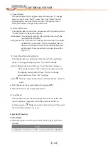
Start
the
engine,
and
note
the
voltage
readings
at
various
engines
speeds
with
the
headlight
turned
on
and
then
turned
off.
The
readings
should
show
nearly
battery
voltage
when
the
engine
speed
is
low,
and
as
the
engine
speed
rises,
the
readings
should
also
rise.
But
they
must
be
kept
under
the
specified
voltage.
Regulator/
Rectifier
Output
Voltage
Connections
Tester
Range
Reading
Tester
(+)
to
Tester
(
‐
)
to
25
V
DC
Battery
(+)
Battery
(
‐
)
14
~
15
V
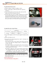
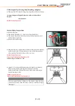
●
Turn
off
the
ignition
switch
to
stop
the
engine,
and
remove
the
seat.
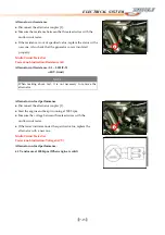
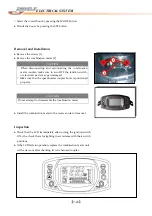
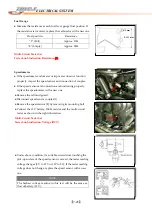
●
Remove
the
battery
stay
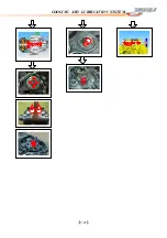
[1].
1
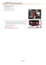
●
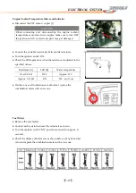
Measure
the
DC
voltage
between
the
(+
)
and
(-
)
terminals
with
the
multi
‐
circuit
tester.
If
the
regulator/rectifier
output
voltage
is
kept
between
the
values
given
in
the
table,
the
charging
system
is
considered
to
be
working
normally.
If
the
output
voltage
is
much
higher
than
the
values
specified
in
the
table,
the
regulator/rectifier
is
defective
or
the
regulator
/rectifier
leads
are
loose
or
open.
If
the
battery
voltage
does
not
rise
as
the
engine
speed
increases,
then
the
regulator/rectified
is
defective
or
the
alternator
output
is
insufficient
for
the
loads,
check
the
alternator
and
regulator/rectifier
to
determine
which
part
is
defective.
+
-
NOTE
When
making
this
test,
be
sure
that
the
battery
is
in
fully
‐
charged
condition.
Multi
‐
Circuit
Tester
Set
Tester
knob
indication:
Voltage
(DCV)
Содержание DL-702 2008
Страница 1: ...FOREWORD INDEX 0 0...
Страница 41: ...3 11 BRAKE...
Страница 180: ...6 70 ENGINE Install the starter motor...
Страница 201: ...7 21 COOLING AND LUBRICATION SYSTEM Engine Lubrication System Chart...
Страница 202: ...7 22 COOLING AND LUBRICATION SYSTEM Engine Lubrication System 1 2 3 1 2 3 1 2 3...
Страница 203: ...7 23 COOLING AND LUBRICATION SYSTEM 1 2 3...
Страница 205: ...7 2 ELECTRICAL SYSTEM Fuses 7 30 Main Fuse Removal 7 30 Fuse Inspection 7 30 Switches 7 31 Wiring Diagram 7 32...
Страница 235: ...7 32 ELECTRICAL SYSTEM Wiring Diagram...
Страница 236: ...7 33 ELECTRICAL SYSTEM Wiring Diagram...
Страница 237: ...7 34 7 34 ELECTRICAL SYSTEM ELECTRICAL SYSTEM...
Страница 238: ...7 35 ELECTRICAL SYSTEM NOTE...
Страница 240: ...9 2 PERIODIC MAINTENANCE...
Страница 246: ...9 8 PERIODIC MAINTENANCE Intake Side...
Страница 247: ...9 9 PERIODIC MAINTENANCE Exhaust Side Side...
Страница 270: ...9 32 PERIODIC MAINTENANCE 1 2 3 4 18 19 12 16 17 21 13 14 15 22 23 5 6 7 8 9 12 10 11 20...

