【
6-16
】
ENGINE
●
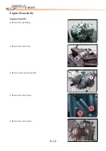
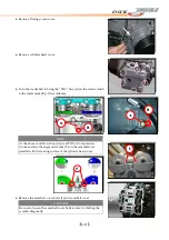
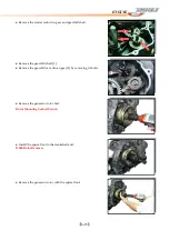
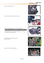
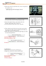
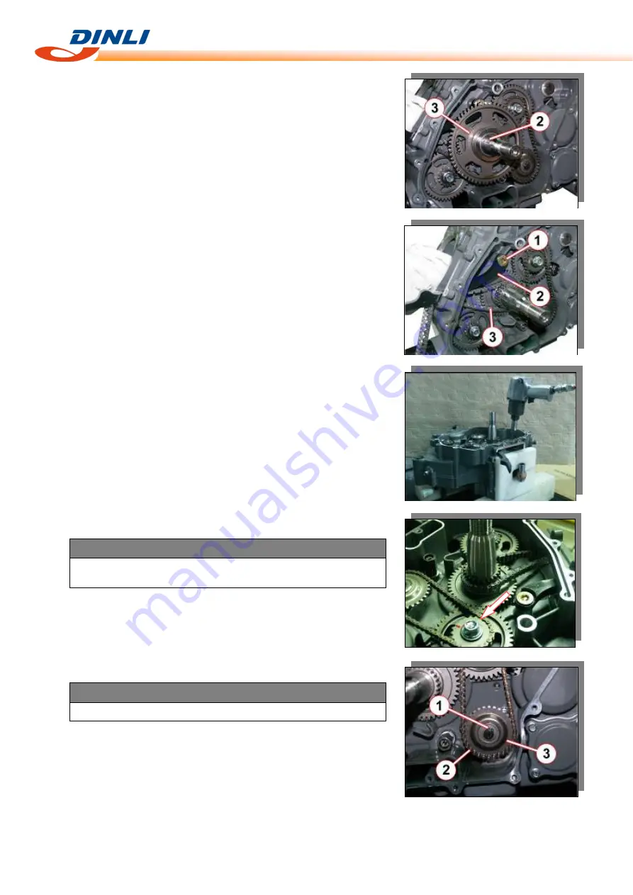
Remove
the
key
[2].
●
Remove
the
starter
driven
gear
[3].
●
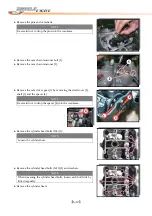
Remove
the
cam
chain
guide
bolt
[1],
cam
chain
guide
[2].
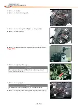
●
Remove
the
cam
chain
[3].
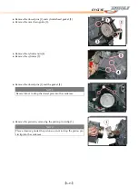
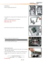
●
Remove
the
balancer
shaft
driven
gear
bolts
with
the
special
tool.
Stopper
Plate
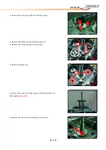
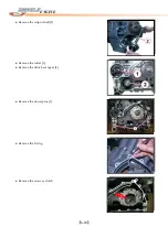
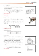
●
Remove
the
oil
pump
driven
gear.
CAUTION
The
oil
pump
drive
gear
and
the
oil
pump
driven
gear
must
removed
at
the
same
time.
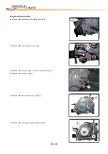
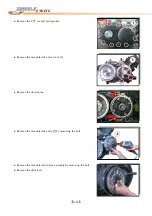
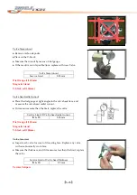
●
Remove
the
snap
ring
[1].
NOTE
Be
careful
not
to
drop
the
snap
ring
[1]
into
the
crankcase.
●
Remove
the
oil
pump
drive
chain
[2]
and
oil
pump
driven
gear
[3].
Содержание DL-702 2008
Страница 1: ...FOREWORD INDEX 0 0...
Страница 41: ...3 11 BRAKE...
Страница 180: ...6 70 ENGINE Install the starter motor...
Страница 201: ...7 21 COOLING AND LUBRICATION SYSTEM Engine Lubrication System Chart...
Страница 202: ...7 22 COOLING AND LUBRICATION SYSTEM Engine Lubrication System 1 2 3 1 2 3 1 2 3...
Страница 203: ...7 23 COOLING AND LUBRICATION SYSTEM 1 2 3...
Страница 205: ...7 2 ELECTRICAL SYSTEM Fuses 7 30 Main Fuse Removal 7 30 Fuse Inspection 7 30 Switches 7 31 Wiring Diagram 7 32...
Страница 235: ...7 32 ELECTRICAL SYSTEM Wiring Diagram...
Страница 236: ...7 33 ELECTRICAL SYSTEM Wiring Diagram...
Страница 237: ...7 34 7 34 ELECTRICAL SYSTEM ELECTRICAL SYSTEM...
Страница 238: ...7 35 ELECTRICAL SYSTEM NOTE...
Страница 240: ...9 2 PERIODIC MAINTENANCE...
Страница 246: ...9 8 PERIODIC MAINTENANCE Intake Side...
Страница 247: ...9 9 PERIODIC MAINTENANCE Exhaust Side Side...
Страница 270: ...9 32 PERIODIC MAINTENANCE 1 2 3 4 18 19 12 16 17 21 13 14 15 22 23 5 6 7 8 9 12 10 11 20...

