【
7-9
】
COOLING AND LUBRICATION SYSTEM
Cooling
Fan
Thermo
‐
Switch
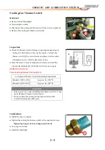
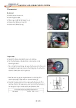
Removal
●
Remove
the
left
headlight.
●
Drain
engine
coolant.
●
Disconnect
the
cooling
fan
thermo
‐
switch
lead
wire
coupler
[1].
●
Remove
the
cooling
fan
thermo
‐
switch
[2].
Inspection
●
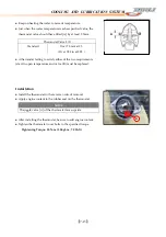
Check
the
thermo
‐
switch
closing
or
opening
temperatures
by
testing
it
at
the
bench
as
shown
in
the
figure.
Connect
the
thermo
‐
switch
[1]
to
a
circuit
tester
and
place
it
in
the
water
contained
in
a
pan,
which
is
placed
on
a
stove.
●
Heat
the
water
to
raise
its
temperature
slowly
and
read
the
column
thermometer
[2]
when
the
switch
closes
or
opens.
Multi
‐
circuit
tester
set
Tester
knob
indication:
Continuity
test
Installation
●
Install
the
new
O
‐
ring
[1].
●
Tighten
the
cooling
fan
thermo
‐
switch
to
the
specified
torque.
Tightening
Torque:
25
N
‐
m
(2.5kgf
‐
m,
18.0
lb
‐
ft)
●
Pour
engine
coolant.
●
Install
the
headlight.
Cooling
Fan
Thermo
‐
Switch
Operating
Temperature
Standard
(OFF
to
ON)
Approx.
96
(205
℉
)
Standard
(ON
to
OFF)
Approx.
86
(187
℉
)
CAUTION
○
Take
special
care
when
handling
the
thermo
‐
switch.
It
may
cause
damage
if
it
gets
a
sharp
impact.
○
Do
not
contact
the
cooling
fan
thermo
‐
switch
and
the
column
thermometer
with
a
pan
1
2
1
2
1
Содержание DL-702 2008
Страница 1: ...FOREWORD INDEX 0 0...
Страница 41: ...3 11 BRAKE...
Страница 180: ...6 70 ENGINE Install the starter motor...
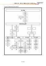
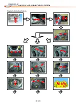
Страница 201: ...7 21 COOLING AND LUBRICATION SYSTEM Engine Lubrication System Chart...
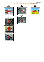
Страница 202: ...7 22 COOLING AND LUBRICATION SYSTEM Engine Lubrication System 1 2 3 1 2 3 1 2 3...
Страница 203: ...7 23 COOLING AND LUBRICATION SYSTEM 1 2 3...
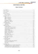
Страница 205: ...7 2 ELECTRICAL SYSTEM Fuses 7 30 Main Fuse Removal 7 30 Fuse Inspection 7 30 Switches 7 31 Wiring Diagram 7 32...
Страница 235: ...7 32 ELECTRICAL SYSTEM Wiring Diagram...
Страница 236: ...7 33 ELECTRICAL SYSTEM Wiring Diagram...
Страница 237: ...7 34 7 34 ELECTRICAL SYSTEM ELECTRICAL SYSTEM...
Страница 238: ...7 35 ELECTRICAL SYSTEM NOTE...
Страница 240: ...9 2 PERIODIC MAINTENANCE...
Страница 246: ...9 8 PERIODIC MAINTENANCE Intake Side...
Страница 247: ...9 9 PERIODIC MAINTENANCE Exhaust Side Side...
Страница 270: ...9 32 PERIODIC MAINTENANCE 1 2 3 4 18 19 12 16 17 21 13 14 15 22 23 5 6 7 8 9 12 10 11 20...

