


【
7-23
】
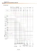
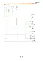
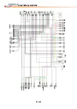
ELECTRICAL SYSTEM
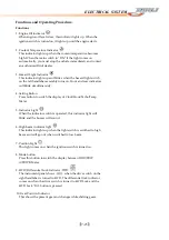
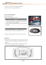
Functions
and
Operating
Procedure
Functions
1.
Engine
Oil
indicator
When
engine
oil
level
is
low,
this
indicator
lights
up.
When
the
ignition
switch
is
turned
on,
it
lights
up
until
the
engine
starts.
2.
Coolant
Temperature
Indicator
This
indicator
lights
up
when
the
coolant
temperature
becomes
high.
When
the
main
switch
in
“ON”
if
the
light
comes
on
automatically,
you
must
stop
the
vehicle
immediately
and
contact
an
authorized
Dinli
dealer.
3.
Hazard
Light
Indicator
This
indicator
lights
up
and
blinks
when
the
hazard
light
switch
on
the
left
handlebar
assembly
turns
on.
Front
and
rear
indicators
will
blink
simultaneously.
4.
Setting
Button
Press
button
to
switch
the
display
of
Clock/Hour/Tacho/Temp
Meter.
5.
Indicator
Light
When
the
indicator
switch
is
operated,
this
indicator
light
will
blink
and
the
buzzer
will
sound.
6.
High
beam
indicator
light
This
indicator
lights
up
when
the
light
switch
is
switched
to
high
beam
and
will
go
out
when
switched
to
low
beam.
7.
Position
Light
This
light
comes
on
when
the
ignition
switch
is
turned
on.
8.
Mode
button
Press
this
button
to
switch
the
display
between
ODO/TRIP
A/TRIP
B
Meter.
9.
4WD/
Differential
Lock
Indicator
The
instrument
panel
shows
when
the
drive
switch
on
the
right
handlebar
is
turned
to
4WD.
The
differential
lock
indicator
comes
on
when
the
drive
switch
is
turned
to
4WD
Lock
and
the
4WD
Lock
“On”
button
is
pressed.
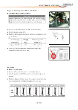
10.
Gear
Position
Indicator
This
shows
the
present
gear
and
changes
while
shifting
gears.
Содержание DL-702 2008
Страница 1: ...FOREWORD INDEX 0 0...
Страница 41: ...3 11 BRAKE...
Страница 180: ...6 70 ENGINE Install the starter motor...
Страница 201: ...7 21 COOLING AND LUBRICATION SYSTEM Engine Lubrication System Chart...
Страница 202: ...7 22 COOLING AND LUBRICATION SYSTEM Engine Lubrication System 1 2 3 1 2 3 1 2 3...
Страница 203: ...7 23 COOLING AND LUBRICATION SYSTEM 1 2 3...
Страница 205: ...7 2 ELECTRICAL SYSTEM Fuses 7 30 Main Fuse Removal 7 30 Fuse Inspection 7 30 Switches 7 31 Wiring Diagram 7 32...
Страница 235: ...7 32 ELECTRICAL SYSTEM Wiring Diagram...
Страница 236: ...7 33 ELECTRICAL SYSTEM Wiring Diagram...
Страница 237: ...7 34 7 34 ELECTRICAL SYSTEM ELECTRICAL SYSTEM...
Страница 238: ...7 35 ELECTRICAL SYSTEM NOTE...
Страница 240: ...9 2 PERIODIC MAINTENANCE...
Страница 246: ...9 8 PERIODIC MAINTENANCE Intake Side...
Страница 247: ...9 9 PERIODIC MAINTENANCE Exhaust Side Side...
Страница 270: ...9 32 PERIODIC MAINTENANCE 1 2 3 4 18 19 12 16 17 21 13 14 15 22 23 5 6 7 8 9 12 10 11 20...


