


【
9-7
】
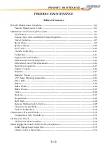
PERIODIC MAINTENANCE
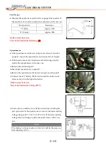
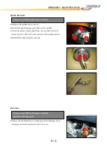
Valve Clearance Adjustment
●
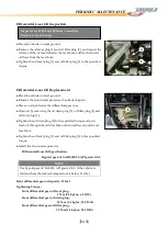
The clearance is adjusted by replacing the existing tappet shim by
a thicker or thinner one.
●
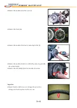
Remove the intake or exhaust camshaft. (See Engine Chapter)
●
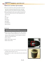
Remove the tappet and shim by fingers or magnetic hand.
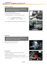
●
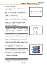
Check the figures printed on the shim. These figures indicate the
thickness of the shim, as illustrated.
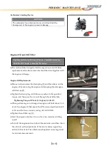
●
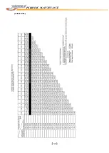
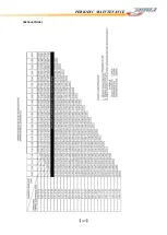
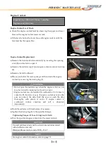
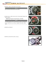
Select a replacement shim that will provide a clearance within the
specified range. For the purpose of this adjustment, a total of 21
sizes of tappet shim are available ranging from 2.50 to 3.50 mm in
steps of 0.05 mm. Fit the selected shim to the valve stem end, with
numbers towards tappet. Be sure to check shim size with
micrometer to ensure its size. Refer to the tappet shim selection
table for details in the following pages.
●
After replacing the tappet shim and camshafts, rotate the engine
so that the tappet is depressed fully. This will squeeze out oil
trapped between the shim and the tappet that could cause an
incorrect measurement. Then check the clearance again to confirm
that it is within the specified range.
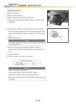
●
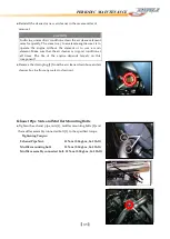
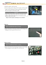
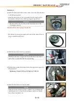
Install the new gasket [1] to the cylinder head cover.
●
Apply BOND to the cam end caps of the gasket as shown.
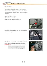
●
Tighten the head cover bolts to the specified two-step torque
sequentially and diagonally.
Tightening Torque
:
Initial 10 N-m
Final 14 N-m
NOTE
○
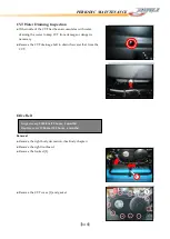
Be sure to apply engine oil to tappet shim top and bottom
faces.
○
When seating the tappet shim, be sure the figure printed
surface faces the tappet.
NOTE
Reinstall the camshafts in the specified manner.
(See Engine Chapter)
CAUTION
Use the new gasket to prevent oil leakage.
NOTE
Apply engine oil to the both side of head cover washer before
installing the head cover bolts.
1
Содержание DL-702 2008
Страница 1: ...FOREWORD INDEX 0 0...
Страница 41: ...3 11 BRAKE...
Страница 180: ...6 70 ENGINE Install the starter motor...
Страница 201: ...7 21 COOLING AND LUBRICATION SYSTEM Engine Lubrication System Chart...
Страница 202: ...7 22 COOLING AND LUBRICATION SYSTEM Engine Lubrication System 1 2 3 1 2 3 1 2 3...
Страница 203: ...7 23 COOLING AND LUBRICATION SYSTEM 1 2 3...
Страница 205: ...7 2 ELECTRICAL SYSTEM Fuses 7 30 Main Fuse Removal 7 30 Fuse Inspection 7 30 Switches 7 31 Wiring Diagram 7 32...
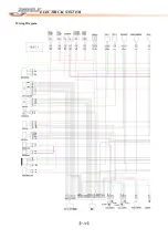
Страница 235: ...7 32 ELECTRICAL SYSTEM Wiring Diagram...
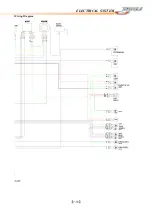
Страница 236: ...7 33 ELECTRICAL SYSTEM Wiring Diagram...
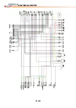
Страница 237: ...7 34 7 34 ELECTRICAL SYSTEM ELECTRICAL SYSTEM...
Страница 238: ...7 35 ELECTRICAL SYSTEM NOTE...
Страница 240: ...9 2 PERIODIC MAINTENANCE...
Страница 246: ...9 8 PERIODIC MAINTENANCE Intake Side...
Страница 247: ...9 9 PERIODIC MAINTENANCE Exhaust Side Side...
Страница 270: ...9 32 PERIODIC MAINTENANCE 1 2 3 4 18 19 12 16 17 21 13 14 15 22 23 5 6 7 8 9 12 10 11 20...


