
【
3-4
】
BRAKE
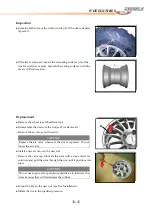
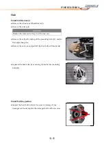
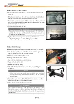
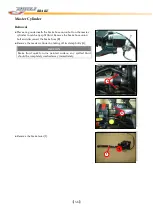
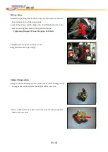
Brake Fluid Level Inspection
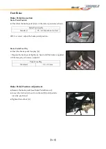
● Position the reservoir horizontal, and check the fluid level in the
reservoir.
★
If the fluid level is lower than the lower level line, check for fluid
leakage of the brake line, and add the fluid as follow.
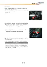
○
Removal the reservoir cap, and fill the reservoir to the upper level
line [A] in the reservoir with the same type and brand of the fluid
that is already in the reservoir.
And then install the reservoir cap.
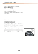
●
Tighten the reservoir cap screws to the specified torque:
Tightening Torque: 1.5 N-m (0.15 kg-m, 13 in-lb)
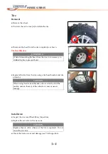
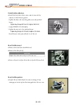
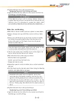
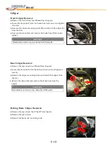
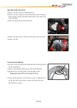
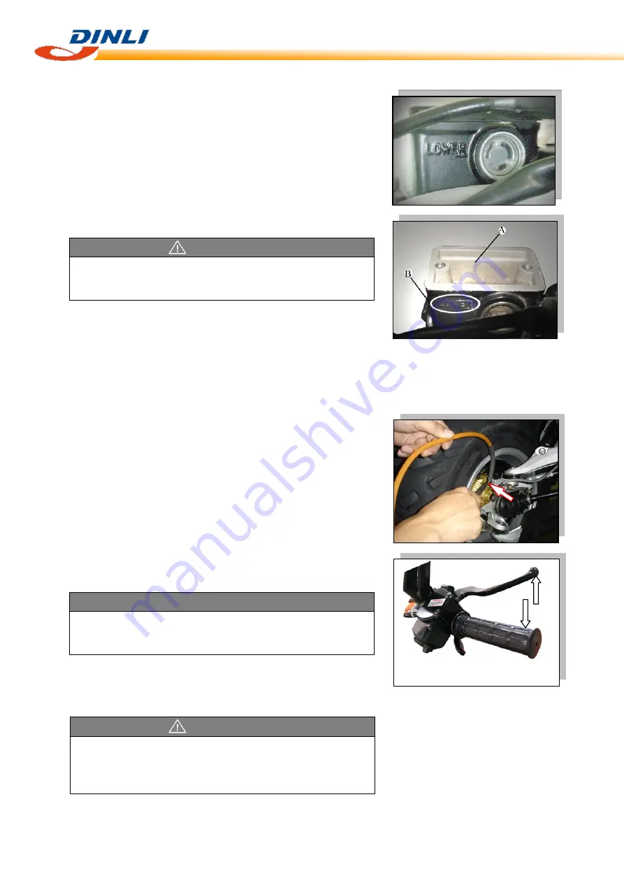
Brake Fluid Change
●
Remove the reservoir cap and the rubber cap on the bleed valve.
●
Attach a clear plastic hose to the bleed valve on the caliper, and
run the other end of the hose into a container.
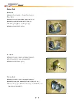
●
Fill the reservoir with new brake fluid.
●
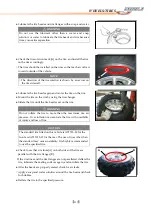
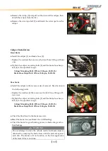
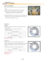
Change the brake fluid as follows:
○
Open the bleed valve in counterclockwise.
○
Squeeze the brake leve
r [B].
○
Release the brake lever [A].
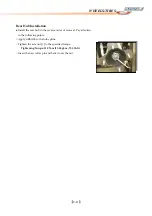
●
Check the fluid level in the reservoir often, replenishing it as
necessary.
●
Repeat this operation until fresh brake fluid comes out into the
plastic hose or the color of the fluid change.
●
Close the bleed valve in clockwise direction.
WARNING
Change the fluid in the brake line completely if the fluid must
be refilled but the type and brand of the fluid that is already in
the reservoir are unidentified.
A
B
NOTE
○
If the fluid in the reservoir runs completely out any time
during fluid change, air will enter the line, and the system
must be bled.
WARNING
Do not mix two brand of fluid. Change the brake fluid in the
brake line completely if the fluid must be refilled but the type
and brand of the brake fluid that is already in the reservoir are
unidentified.
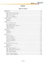
Содержание DL-702 2008
Страница 1: ...FOREWORD INDEX 0 0...
Страница 41: ...3 11 BRAKE...
Страница 180: ...6 70 ENGINE Install the starter motor...
Страница 201: ...7 21 COOLING AND LUBRICATION SYSTEM Engine Lubrication System Chart...
Страница 202: ...7 22 COOLING AND LUBRICATION SYSTEM Engine Lubrication System 1 2 3 1 2 3 1 2 3...
Страница 203: ...7 23 COOLING AND LUBRICATION SYSTEM 1 2 3...
Страница 205: ...7 2 ELECTRICAL SYSTEM Fuses 7 30 Main Fuse Removal 7 30 Fuse Inspection 7 30 Switches 7 31 Wiring Diagram 7 32...
Страница 235: ...7 32 ELECTRICAL SYSTEM Wiring Diagram...
Страница 236: ...7 33 ELECTRICAL SYSTEM Wiring Diagram...
Страница 237: ...7 34 7 34 ELECTRICAL SYSTEM ELECTRICAL SYSTEM...
Страница 238: ...7 35 ELECTRICAL SYSTEM NOTE...
Страница 240: ...9 2 PERIODIC MAINTENANCE...
Страница 246: ...9 8 PERIODIC MAINTENANCE Intake Side...
Страница 247: ...9 9 PERIODIC MAINTENANCE Exhaust Side Side...
Страница 270: ...9 32 PERIODIC MAINTENANCE 1 2 3 4 18 19 12 16 17 21 13 14 15 22 23 5 6 7 8 9 12 10 11 20...


