ENGINE
【
6-43
】
●
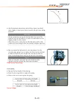
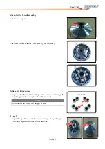
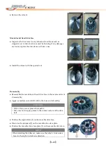
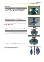
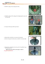
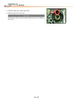
Install
the
spacer.
NOTE
When
inserting
the
spacer,
press
down
the
movable
drive
face
plate
so
as
not
to
cause
the
rollers
to
come
out
of
position.
Movable
driven
face
disassembly
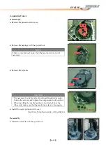
●
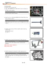
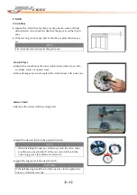
Hold
the
movable
driven
face
assembly
with
the
special
tool,
loosen
the
movable
driven
face
ring
nut
with
the
special
tools.
WARNING
Do
not
remove
the
movable
driven
face
ring
nut
before
attaching
the
clutch
spring
compressor.
Ring
Nut
Socket
Wrench
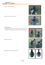
●
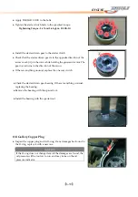
Attach
the
special
tool
to
the
movable
driven
face
assembly
and
compress
the
movable
driven
face
assembly
by
turning
in
the
special
tool
handle.
NOTE
Make
sure
to
insert
the
flange
of
the
special
tool
into
the
spring
plate
hole.
●
Remove
the
movable
driven
face
ring
nut.
●
Loosen
the
special
tool
handle
slowly
and
remove
the
special
tool.
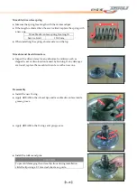
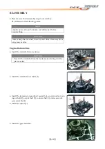
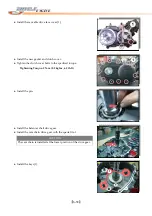
●
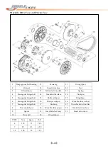
Remove
the
spring
plate
[1]
and
spring
[2].
●
Remove
the
spring
seat
[3].
Содержание DL-702 2008
Страница 1: ...FOREWORD INDEX 0 0...
Страница 41: ...3 11 BRAKE...
Страница 180: ...6 70 ENGINE Install the starter motor...
Страница 201: ...7 21 COOLING AND LUBRICATION SYSTEM Engine Lubrication System Chart...
Страница 202: ...7 22 COOLING AND LUBRICATION SYSTEM Engine Lubrication System 1 2 3 1 2 3 1 2 3...
Страница 203: ...7 23 COOLING AND LUBRICATION SYSTEM 1 2 3...
Страница 205: ...7 2 ELECTRICAL SYSTEM Fuses 7 30 Main Fuse Removal 7 30 Fuse Inspection 7 30 Switches 7 31 Wiring Diagram 7 32...
Страница 235: ...7 32 ELECTRICAL SYSTEM Wiring Diagram...
Страница 236: ...7 33 ELECTRICAL SYSTEM Wiring Diagram...
Страница 237: ...7 34 7 34 ELECTRICAL SYSTEM ELECTRICAL SYSTEM...
Страница 238: ...7 35 ELECTRICAL SYSTEM NOTE...
Страница 240: ...9 2 PERIODIC MAINTENANCE...
Страница 246: ...9 8 PERIODIC MAINTENANCE Intake Side...
Страница 247: ...9 9 PERIODIC MAINTENANCE Exhaust Side Side...
Страница 270: ...9 32 PERIODIC MAINTENANCE 1 2 3 4 18 19 12 16 17 21 13 14 15 22 23 5 6 7 8 9 12 10 11 20...

