ENGINE
【
6-61
】
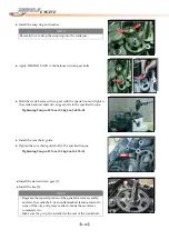
●
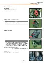
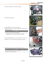
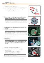
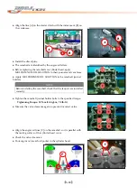
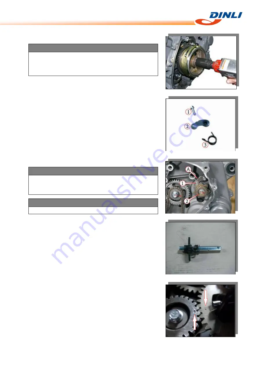
Install
the
generator
rotor
assembly.
CAUTION
Make
sure
that
the
one
way
clutch
on
the
crankshaft
rotor
is
fitted
into
the
generator
rotor
properly,
there
had
to
have
a
small
amount
of
clearance
between
the
rotor
and
the
starter
driven
gear.
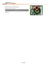
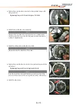
●
Tighten
the
generator
rotor
nut
to
the
specified
torque.
Tightening
Torque:
160
N
‐
m
(16.0
kgf
‐
m,
115
lb
‐
ft)
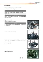
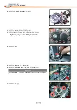
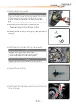
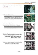
●
Install
the
gearshift
cam
stopper,
the
stopper
[1],
bolts
[2]
and
return
spring
[3].
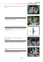
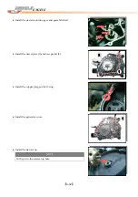
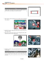
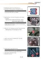
●
Install
the
gearshift
cam
stopper
[1]
and
cam
driven
gear
[2].
NOTE
Hook
the
return
spring
end
[A]
to
the
stopper.
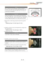
○
Check
the
gearshift
cam
stopper
moves
smoothly.
○
Locate
the
gearshift
cam
in
the
neutral
position.
NOTE
Align
the
gearshift
cam
pin
with
the
cam
driven
gear
hole.
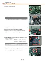
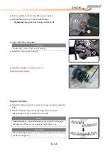
●
Reassemble
the
gearshift
shaft.
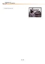
●
Install
the
gearshift
by
aligning
the
punched
mark
with
the
center
of
the
cam
driven
gear.
Содержание DL-702 2008
Страница 1: ...FOREWORD INDEX 0 0...
Страница 41: ...3 11 BRAKE...
Страница 180: ...6 70 ENGINE Install the starter motor...
Страница 201: ...7 21 COOLING AND LUBRICATION SYSTEM Engine Lubrication System Chart...
Страница 202: ...7 22 COOLING AND LUBRICATION SYSTEM Engine Lubrication System 1 2 3 1 2 3 1 2 3...
Страница 203: ...7 23 COOLING AND LUBRICATION SYSTEM 1 2 3...
Страница 205: ...7 2 ELECTRICAL SYSTEM Fuses 7 30 Main Fuse Removal 7 30 Fuse Inspection 7 30 Switches 7 31 Wiring Diagram 7 32...
Страница 235: ...7 32 ELECTRICAL SYSTEM Wiring Diagram...
Страница 236: ...7 33 ELECTRICAL SYSTEM Wiring Diagram...
Страница 237: ...7 34 7 34 ELECTRICAL SYSTEM ELECTRICAL SYSTEM...
Страница 238: ...7 35 ELECTRICAL SYSTEM NOTE...
Страница 240: ...9 2 PERIODIC MAINTENANCE...
Страница 246: ...9 8 PERIODIC MAINTENANCE Intake Side...
Страница 247: ...9 9 PERIODIC MAINTENANCE Exhaust Side Side...
Страница 270: ...9 32 PERIODIC MAINTENANCE 1 2 3 4 18 19 12 16 17 21 13 14 15 22 23 5 6 7 8 9 12 10 11 20...

