【
4-26
】
SUSPENSION/STEERING/DRIVE SHAFT
●
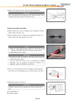
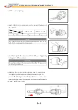
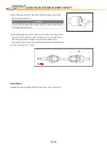
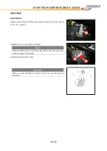
Insert the cage into the outer race and fit a stopper ring in the
groove of the outer race.
●
After fitting the boot on the outer race, insert a screw driver into
the boot on the outer race side and allow air to enter the boot so
that the air pressure in the boot becomes the same as the
atmospheric pressure at the positions indicated in the illustration.
[A] 188 – 198 mm (7.4 – 7.8 in)
Installation
●
Install the rear propeller shaft in the reverse order of removal.
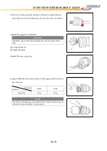
CAUTION
Locate the opening of the stopper ring [1] so that the opening is
not lined up with a ball.
1
A
B
Содержание DL-702 2008
Страница 1: ...FOREWORD INDEX 0 0...
Страница 41: ...3 11 BRAKE...
Страница 180: ...6 70 ENGINE Install the starter motor...
Страница 201: ...7 21 COOLING AND LUBRICATION SYSTEM Engine Lubrication System Chart...
Страница 202: ...7 22 COOLING AND LUBRICATION SYSTEM Engine Lubrication System 1 2 3 1 2 3 1 2 3...
Страница 203: ...7 23 COOLING AND LUBRICATION SYSTEM 1 2 3...
Страница 205: ...7 2 ELECTRICAL SYSTEM Fuses 7 30 Main Fuse Removal 7 30 Fuse Inspection 7 30 Switches 7 31 Wiring Diagram 7 32...
Страница 235: ...7 32 ELECTRICAL SYSTEM Wiring Diagram...
Страница 236: ...7 33 ELECTRICAL SYSTEM Wiring Diagram...
Страница 237: ...7 34 7 34 ELECTRICAL SYSTEM ELECTRICAL SYSTEM...
Страница 238: ...7 35 ELECTRICAL SYSTEM NOTE...
Страница 240: ...9 2 PERIODIC MAINTENANCE...
Страница 246: ...9 8 PERIODIC MAINTENANCE Intake Side...
Страница 247: ...9 9 PERIODIC MAINTENANCE Exhaust Side Side...
Страница 270: ...9 32 PERIODIC MAINTENANCE 1 2 3 4 18 19 12 16 17 21 13 14 15 22 23 5 6 7 8 9 12 10 11 20...


