


CHAPTER 3 THEORY OF OPERATION
3-16
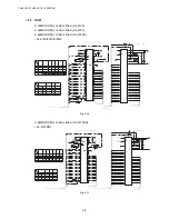
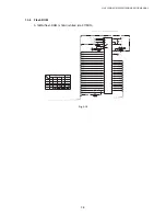
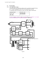
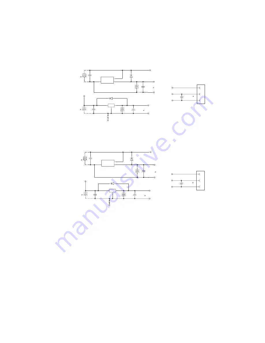
1.3.14 Power
Supply
+5V is generated by the 3-pin regulator from astable 7V (8V) supplied from the LVPS. +5V is
used for the IEEE1284 interface, the LD PCB and the engine PCB. In addition, +1.9V is
generated by the 3-pin regulator from 3.3V supplied from the LVPS. +1.9V is used for the
CPU within the ASIC and the logic circuit.
<HL-5130/5140/5150D>
+
+
+
+
+
VDD7
0V
C115
C220
6.3V 6V
VDD3
B3B-EH
1
+3V
CN7
2
+7V
3
0V
VDD7
D2
RB751V-40
0V
VDD5
Q3 NJM2391DL1-05
OUT
VCC
GND
C114
C22
16V
C116
C104
FG1
OT1
C103
C10
16V
C122
C104
0V
VDD1.8
Q2
NJU7223DL1-19
1
OUT
2
VCC
3
GND
C100
C104
C89
C10
16V
D1
RB751V-40
C101
C220
6.3V 6V
VDD3
C93
C104
LVPS
Fig. 3-27
<HL-5170DN>
+
+
+
+
+
VDD7
D2
RB751V-40
0V
VDD5
Q6 NJM2391DL1-19
OUT
VCC
GND
C157
C22
16V
C151
C104
FG1
OT1
C140
C10
16V
C158
C104
VDD7
0V
C141
C220
6.3V 6V
VDD3
B3B-EH
1
+3V
CN8
2
+7V
3
0V
C138
C220
6.3V 6V
VDD3
C128
C104
0V
VDD1.8
Q5
NJU7223DL1-19
1
OUT
2
VCC
3
GND
C137
C104
C125
C10
16V
D1
RB751V-40
LVPS
Fig. 3-28
Содержание HL-5130
Страница 114: ...HL 5130 5140 5150D 5150DN Service Manual 4 13 24 Remove the paper rear guide Fig 4 20 Paper tray Paper rear guide 2 1 1 ...
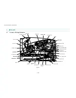
Страница 271: ...APPENDIX A 9 Appendix 9 Engine PCB Circuit Diagram 1 2 NAME CODE B512153CIR 1 2 LJ923001 A 9 ...
Страница 272: ...APPENDIX A 10 Appendix 10 Engine PCB Circuit Diagram 2 2 NAME CODE B512153CIR 2 2 LJ923001 A 10 ...
Страница 273: ...APPENDIX A 11 Appendix 11 Low voltage Power Supply PCB Circuit Diagram 120V NAME Low voltage PS Circuit 120V A 11 ...
Страница 274: ...APPENDIX A 12 Appendix 12 Low voltage Power Supply PCB Circuit Diagram 230V NAME Low voltage PS Circuit 230V A 12 ...
Страница 275: ...APPENDIX A 13 Appendix 13 High voltage Power Supply PCB Circuit Diagram NAME High voltage PS Circuit A 13 ...


