


CHAPTER 2 INSTALLATION AND BASIC OPERATION
2-20
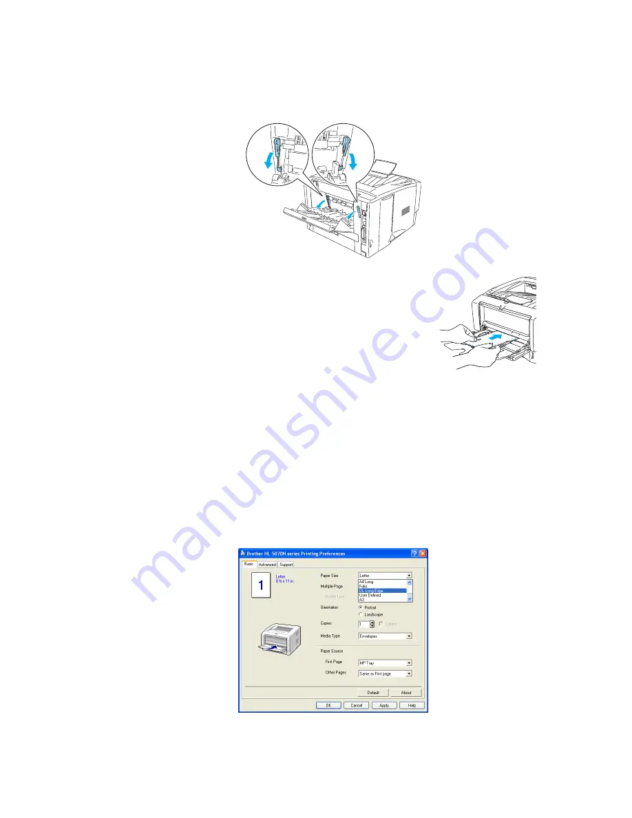
NOTE: <Envelopes that have been creased after they have been printed>
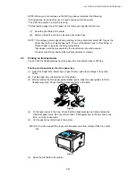
At the back of the printer, open the back output tray and push down the blue tabs at the left
and right hand sides (as shown in the figure below). When you have finished printing your
envelopes, close the back output tray to reset the two blue tabs back to their original position.
Fig.2-23
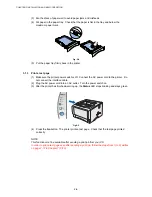
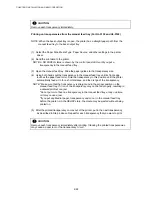
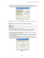
(5) Put the envelopes in the MP tray so that they touch the back of
the tray and remain under the maximum paper height guides on
both sides of the tray. Do not put more than 3 envelopes in the
MP tray at any one time, or it may cause a jam.
Fig.2-24
NOTE;
•
Make sure that the envelope are neatly stacked and in the proper position in the MP tray.
If they are not, the envelopes may not be fed properly, resulting in a skewed printout or a
jam.
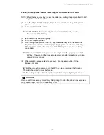
(6) Press and slide the paper-width guide to fit the envelope size.
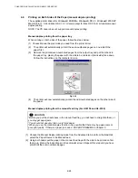
NOTE: DL size double-flap envelopes
If the DL size double flap envelope is creased after printing, go to the Basic tab, select Paper
Size and then select DL Long Edge. Put a new DL size double-flap envelope in the MP tray
with the longest edge of the envelope in first, then print again.
Fig.2-25
Содержание HL-5130
Страница 114: ...HL 5130 5140 5150D 5150DN Service Manual 4 13 24 Remove the paper rear guide Fig 4 20 Paper tray Paper rear guide 2 1 1 ...
Страница 271: ...APPENDIX A 9 Appendix 9 Engine PCB Circuit Diagram 1 2 NAME CODE B512153CIR 1 2 LJ923001 A 9 ...
Страница 272: ...APPENDIX A 10 Appendix 10 Engine PCB Circuit Diagram 2 2 NAME CODE B512153CIR 2 2 LJ923001 A 10 ...
Страница 273: ...APPENDIX A 11 Appendix 11 Low voltage Power Supply PCB Circuit Diagram 120V NAME Low voltage PS Circuit 120V A 11 ...
Страница 274: ...APPENDIX A 12 Appendix 12 Low voltage Power Supply PCB Circuit Diagram 230V NAME Low voltage PS Circuit 230V A 12 ...
Страница 275: ...APPENDIX A 13 Appendix 13 High voltage Power Supply PCB Circuit Diagram NAME High voltage PS Circuit A 13 ...


