


HL-5130/5140/5150D/5170DN SERVICE MANUAL
3-17
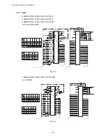
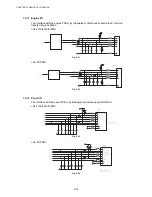
1.4 Engine
PCB
The gate array which transforms the serial signal from the main PCB into the parallel signal is
mounted on the engine PCB.
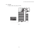
The engine PCB controls the following parts by using the transferred signal data;
•
Main motor
•
Upper cassette sensor
•
Fan motor
•
Lower cassette sensor
•
Thermistor
•
Upper paper exit sensor
•
Polygon motor
•
Lower paper exit sensor
•
High-voltage power supply
•
Lower cassette exit sensor
•
Toner sensor
•
Paper eject sensor
•
Cover sensor
•
Fixing unit cover sensor
•
Front registration sensor
•
Multi-purpose tray paper exit sensor
•
Rear registration sensor
•
DX sensor
•
Solenoid
•
DX rear cover sensor
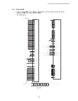
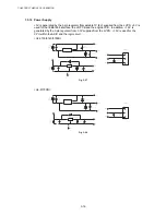
For the circuit diagram of the engine PCB, see
APPENDIX 9. and 10. ‘ENGINE PCB CIRCUIT
DIAGRAM’
in this manual.
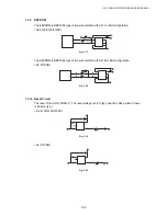
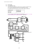
Sensor configuration varies according to machine types.
HL-5130
HL-5140
HL-5150D
/5170DN
Upper cassette sensor
Upper paper exit sensor
Lower cassette sensor
Lower paper exit sensor
Lower cassette exit sensor
Multi-purpose tray paper exit sensor
: Built-in
: Not built-in
Содержание HL-5130
Страница 114: ...HL 5130 5140 5150D 5150DN Service Manual 4 13 24 Remove the paper rear guide Fig 4 20 Paper tray Paper rear guide 2 1 1 ...
Страница 271: ...APPENDIX A 9 Appendix 9 Engine PCB Circuit Diagram 1 2 NAME CODE B512153CIR 1 2 LJ923001 A 9 ...
Страница 272: ...APPENDIX A 10 Appendix 10 Engine PCB Circuit Diagram 2 2 NAME CODE B512153CIR 2 2 LJ923001 A 10 ...
Страница 273: ...APPENDIX A 11 Appendix 11 Low voltage Power Supply PCB Circuit Diagram 120V NAME Low voltage PS Circuit 120V A 11 ...
Страница 274: ...APPENDIX A 12 Appendix 12 Low voltage Power Supply PCB Circuit Diagram 230V NAME Low voltage PS Circuit 230V A 12 ...
Страница 275: ...APPENDIX A 13 Appendix 13 High voltage Power Supply PCB Circuit Diagram NAME High voltage PS Circuit A 13 ...


