


CHAPTER 4 DISASSEMBLY AND RE-ASSEMBLY
4-36
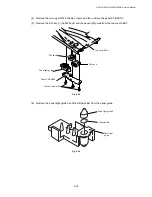
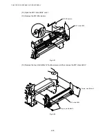
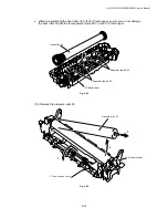
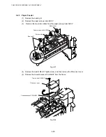
(13) Remove the HR bearing 25.
(14) Remove the HR gear 34.
(15) Remove the HR retaining ring 25.
(16) Remove the heat roller washer 25.
(17) Remove the HR bearing 25.
Fig. 4-62
!
CAUTION:
Never touch the surface of the heat roller.
NOTE:
•
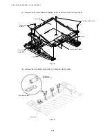
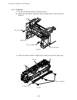
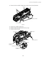
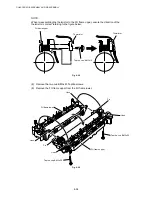
When re-assembling the heat roller 25 to the FU frame upper, place the two projections
onto the bosses on the frame as shown in the figure below.
Fig. 4-63
HR gear 34
HR retaining ring 25
Heat roller 25
HR bearing 25
Heat roller 25
(projection)
HR gear 34
HR bearing 25
(boss)
Heat roller washer 25
HR bearing 25
Содержание HL-5130
Страница 114: ...HL 5130 5140 5150D 5150DN Service Manual 4 13 24 Remove the paper rear guide Fig 4 20 Paper tray Paper rear guide 2 1 1 ...
Страница 271: ...APPENDIX A 9 Appendix 9 Engine PCB Circuit Diagram 1 2 NAME CODE B512153CIR 1 2 LJ923001 A 9 ...
Страница 272: ...APPENDIX A 10 Appendix 10 Engine PCB Circuit Diagram 2 2 NAME CODE B512153CIR 2 2 LJ923001 A 10 ...
Страница 273: ...APPENDIX A 11 Appendix 11 Low voltage Power Supply PCB Circuit Diagram 120V NAME Low voltage PS Circuit 120V A 11 ...
Страница 274: ...APPENDIX A 12 Appendix 12 Low voltage Power Supply PCB Circuit Diagram 230V NAME Low voltage PS Circuit 230V A 12 ...
Страница 275: ...APPENDIX A 13 Appendix 13 High voltage Power Supply PCB Circuit Diagram NAME High voltage PS Circuit A 13 ...


