


CHAPTER 5 PERIODIC MAINTENANCE
5-14
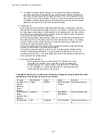
3. PERIODICAL CLEANING
Clean the following parts periodically to avoid any printer problems or print image defects.
!
CAUTION:
While drum unit and scanner window cleaning basically can be implemented by the end user,
the electrical terminals inside the printer and on the drum unit should be cleaned by a service
technician. Instruct the users not to touch those terminals.
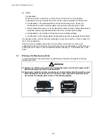
WARNING
There are high voltage electrodes inside the printer. Before cleaning the printer, make
sure that the power switch has been turned off and the power cord has been unplugged
from the power outlet.
3.1
Cleaning the Printer Exterior
Clean the printer exterior to keep the printer clean.
1) Turn off the power switch and unplug the power cord.
2) Wipe dirt and dust away from the printer exterior with a damp cloth and allow the printer
to dry completely before turning the power on again.
3) Plug in the power cord.
!
CAUTION:
•
Use water or neutral detergents for cleaning. Cleaning with volatile liquids such as thinner
or benzene will damage the surface of the printer.
•
Do not use cleaning materials that contain ammonia. They will damage the printer and the
toner cartridge.
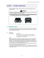
3.2
Cleaning the Drum Unit
When replacing the drum unit or toner cartridge with a new one, be sure to clean the drum
unit.
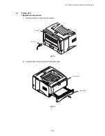
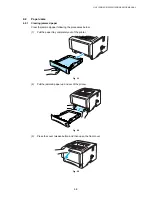
1) Turn off the power switch and unplug the power cord.
2) Press the cover release button, and then open the front cover.
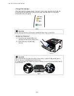
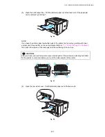
3) Pull out the drum unit assembly.
!
CAUTION:
It is recommended to place the drum unit assembly on a piece of disposable paper or cloth in
case you accidentally spill or scatter toner.
Содержание HL-5130
Страница 114: ...HL 5130 5140 5150D 5150DN Service Manual 4 13 24 Remove the paper rear guide Fig 4 20 Paper tray Paper rear guide 2 1 1 ...
Страница 271: ...APPENDIX A 9 Appendix 9 Engine PCB Circuit Diagram 1 2 NAME CODE B512153CIR 1 2 LJ923001 A 9 ...
Страница 272: ...APPENDIX A 10 Appendix 10 Engine PCB Circuit Diagram 2 2 NAME CODE B512153CIR 2 2 LJ923001 A 10 ...
Страница 273: ...APPENDIX A 11 Appendix 11 Low voltage Power Supply PCB Circuit Diagram 120V NAME Low voltage PS Circuit 120V A 11 ...
Страница 274: ...APPENDIX A 12 Appendix 12 Low voltage Power Supply PCB Circuit Diagram 230V NAME Low voltage PS Circuit 230V A 12 ...
Страница 275: ...APPENDIX A 13 Appendix 13 High voltage Power Supply PCB Circuit Diagram NAME High voltage PS Circuit A 13 ...


