


HL-5130/5140/5150D/5150DN Service Manual
4-53
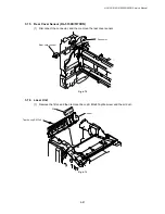
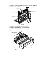
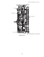
(16) Remove the two cup S M3x6 Taptite screws and the four bind B M4x12 Taptite screws.
(17) Remove the front chute ASSY.
Fig. 4-93
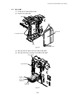
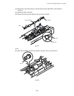
(18) Remove the two shoulder taptite bind B M3x7.5 screws.
(19) Remove the front chute guide assy from the front chute assy.
(20) Remove the front tray chute assy ZL2.
(21) Remove the roller 6, pressure roller shaft and roller 6 guide.
Fig.4-94
Front chute ASSY
Taptite, bind B M4x12
Taptite, bind B M4x12
Taptite, cup S M3x6
Taptite, cup S M3x6
Front chute ASSY
Front tray chute ASSY
Taptite, shoulder bind B
M3x7.5
Front chute guide ASSY
Taptite, shoulder bind B
M3x7.5
Roller 6 guide
1
4
3
2
Roller 6
Pressure roller shaft
Содержание HL-5130
Страница 114: ...HL 5130 5140 5150D 5150DN Service Manual 4 13 24 Remove the paper rear guide Fig 4 20 Paper tray Paper rear guide 2 1 1 ...
Страница 271: ...APPENDIX A 9 Appendix 9 Engine PCB Circuit Diagram 1 2 NAME CODE B512153CIR 1 2 LJ923001 A 9 ...
Страница 272: ...APPENDIX A 10 Appendix 10 Engine PCB Circuit Diagram 2 2 NAME CODE B512153CIR 2 2 LJ923001 A 10 ...
Страница 273: ...APPENDIX A 11 Appendix 11 Low voltage Power Supply PCB Circuit Diagram 120V NAME Low voltage PS Circuit 120V A 11 ...
Страница 274: ...APPENDIX A 12 Appendix 12 Low voltage Power Supply PCB Circuit Diagram 230V NAME Low voltage PS Circuit 230V A 12 ...
Страница 275: ...APPENDIX A 13 Appendix 13 High voltage Power Supply PCB Circuit Diagram NAME High voltage PS Circuit A 13 ...


