


CHAPTER 4 DISASSEMBLY AND RE-ASSEMBLY
4-42
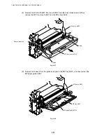
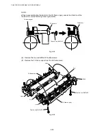
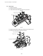
(2) Disconnect the LD harness 5P from the laser unit.
(3) Disconnect the polygon motor harness and remove the sponge from the laser unit.
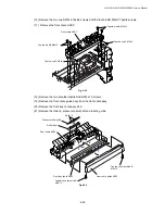
(4) Remove the six cup S M3x8 Taptite screws, and then remove the laser unit.
Fig. 4-74
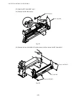
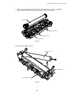
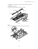
(5) Remove the shutter arm C.
Fig. 4-75
Taptite, cup S M3x8
Taptite, cup S M3x8
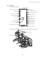
LD harness 5P
Laser unit
Shutter arm C
Frame L
Polygon motor harness
Sponge
Содержание HL-5130
Страница 114: ...HL 5130 5140 5150D 5150DN Service Manual 4 13 24 Remove the paper rear guide Fig 4 20 Paper tray Paper rear guide 2 1 1 ...
Страница 271: ...APPENDIX A 9 Appendix 9 Engine PCB Circuit Diagram 1 2 NAME CODE B512153CIR 1 2 LJ923001 A 9 ...
Страница 272: ...APPENDIX A 10 Appendix 10 Engine PCB Circuit Diagram 2 2 NAME CODE B512153CIR 2 2 LJ923001 A 10 ...
Страница 273: ...APPENDIX A 11 Appendix 11 Low voltage Power Supply PCB Circuit Diagram 120V NAME Low voltage PS Circuit 120V A 11 ...
Страница 274: ...APPENDIX A 12 Appendix 12 Low voltage Power Supply PCB Circuit Diagram 230V NAME Low voltage PS Circuit 230V A 12 ...
Страница 275: ...APPENDIX A 13 Appendix 13 High voltage Power Supply PCB Circuit Diagram NAME High voltage PS Circuit A 13 ...


