


CHAPTER 6 TROUBLESHOOTING
6-22
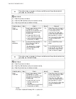
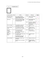
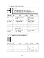
M-9
Fixing Unit failure
Possible cause
Step
Check
Result
Remedy
Poor thermistor
harness contact
1
Is the contact of connector
CN7 on the engine PCB good?
No
Reconnect the connector.
Blown thermal
fuse
2
Remove the fixing unit and
measure the resistance
between the input connectors.
Is it open circuit?
Yes
Replace the fixing unit.
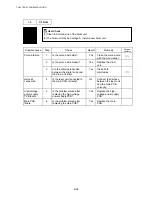
Thermistor
failure
3
Is the thermistor installed
properly?
Yes
Replace the fixing unit.
No
Reinstall the thermistor
properly.
Halogen heater
lamp failure
4
Remove the fixing unit and
measure the resistance of the
halogen heater lamp. Is it
open circuit?
Yes
Replace the halogen heater
lamp.
Heater harness
connection
failure
5
Is the heater harness
connector connected to the
low-voltage power supply PCB
and fixing unit secure?
No
Reconnect the connectors
securely.
NOTE:
•
This problem will be cleared if leaving the printer power ON for ten minutes.
•
If the heater is cooled down sufficiently, this problem may be cleared by turning on the
printer power switch while pressing the Job Cancel button.
Be warned, however, that this
operation will melt the fixing unit if the heater is hot.
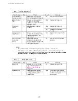
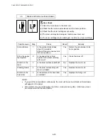
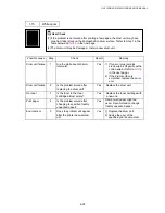
M-10
Main PCB failure
Possible cause
Step
Check
Result
Remedy
Main PCB
1
Is it possible to print the test
page with the method of
1.3.
‘INSPECTION MODE’
in
Chapter 7?
No
Replace the main PCB.
Software bug
2
Does this problem appear
when printing specific data or
printing under a specific
environment?
Yes
Inform the Brother office of
the used specific data, printer
condition and system
environment.
Содержание HL-5130
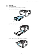
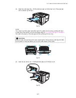
Страница 114: ...HL 5130 5140 5150D 5150DN Service Manual 4 13 24 Remove the paper rear guide Fig 4 20 Paper tray Paper rear guide 2 1 1 ...
Страница 271: ...APPENDIX A 9 Appendix 9 Engine PCB Circuit Diagram 1 2 NAME CODE B512153CIR 1 2 LJ923001 A 9 ...
Страница 272: ...APPENDIX A 10 Appendix 10 Engine PCB Circuit Diagram 2 2 NAME CODE B512153CIR 2 2 LJ923001 A 10 ...
Страница 273: ...APPENDIX A 11 Appendix 11 Low voltage Power Supply PCB Circuit Diagram 120V NAME Low voltage PS Circuit 120V A 11 ...
Страница 274: ...APPENDIX A 12 Appendix 12 Low voltage Power Supply PCB Circuit Diagram 230V NAME Low voltage PS Circuit 230V A 12 ...
Страница 275: ...APPENDIX A 13 Appendix 13 High voltage Power Supply PCB Circuit Diagram NAME High voltage PS Circuit A 13 ...


