


CHAPTER 2 INSTALLATION AND BASIC OPERATION
2-4
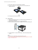
3. INSTALL THE PRINTER
You need to implement hardware setup and driver installation to use the printer.
Firstly, identify the Operating System on your computer. (Windows
®
95/98/Me, Windows NT
®
4.0, Windows
®
2000/XP and Macintosh)Then, purchase the appropriate interface cable
(Parallel, USB or Network) for your computer. Most existing parallel cables support bi-
directional communication, but some might have an incompatible pin assignment or may not
be IEEE 1284-compliant.
The installation programs for the hardware setup and driver installation are contained on the
supplied CD-ROM.
3.1
For All Users
For Windows
users
(1) Turn on the PC power. Insert the supplied CD-ROM into the CD-ROM drive. The
opening screen will appear automatically. Follow the on-screen instructions.
NOTE:
If the opening screen does not appear; click
Start
and select
Run
. Then, enter the CD-drive
letter and type \START.EXE (for example: D:\START.EXE).
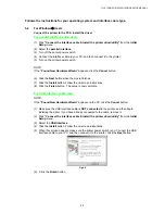
(2) Click
the
Initial Setup
icon on the menu screen.
(3) You can view the Initial Setup instructions.
For Macintosh users
(1) Turn on the Macintosh. Insert the CD-ROM into the CD-ROM drive.
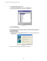
(2) Double click the
Start Here
icon or
Start Here OS X
icon. Follow the on-screen
instructions.
(3) Click the
Initial Setup
icon on the menu screen.
(4) You can view the Initial Setup instructions.
Содержание HL-5130
Страница 114: ...HL 5130 5140 5150D 5150DN Service Manual 4 13 24 Remove the paper rear guide Fig 4 20 Paper tray Paper rear guide 2 1 1 ...
Страница 271: ...APPENDIX A 9 Appendix 9 Engine PCB Circuit Diagram 1 2 NAME CODE B512153CIR 1 2 LJ923001 A 9 ...
Страница 272: ...APPENDIX A 10 Appendix 10 Engine PCB Circuit Diagram 2 2 NAME CODE B512153CIR 2 2 LJ923001 A 10 ...
Страница 273: ...APPENDIX A 11 Appendix 11 Low voltage Power Supply PCB Circuit Diagram 120V NAME Low voltage PS Circuit 120V A 11 ...
Страница 274: ...APPENDIX A 12 Appendix 12 Low voltage Power Supply PCB Circuit Diagram 230V NAME Low voltage PS Circuit 230V A 12 ...
Страница 275: ...APPENDIX A 13 Appendix 13 High voltage Power Supply PCB Circuit Diagram NAME High voltage PS Circuit A 13 ...


