


CHAPTER 3 THEORY OF OPERATION
3-30
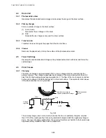
2.6.3 Developing
Developing causes the toner to be attracted to the electrostatic image on the drum so as to
transform it into a visible image.
The developer consists of a non-magnetic toner. The development roller is made of
conductive rubber and the supply roller (which is also made of conductive sponge) rotate
against each other. The toner is charged and carried from the supply roller to the
development roller. The toner adheres to the development roller and is conveyed to the
photosensitive drum at an even thickness controlled by the blade. The toner is nipped
between the development roller and the drum and developed onto the latent image on the
drum. The electrostatic field between the drum and the development roller, which is DC-
biased from the high-voltage power supply, creates the electrostatic potential to attract toner
particles from the development roller to the latent image area on the drum surface.
Fig. 3-47
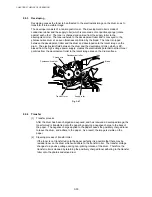
2.6.4 Transfer
(1) Transfer
process
After the drum has been charged and exposed, and has received a developed image, the
toner formed is transferred onto the paper by applying a negative charge to the back of
the paper. The negative charge applied to the paper causes the positively charged toner
to leave the drum, and adhere to the paper. As a result, the image is visible on the
paper.
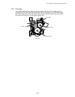
(2) Cleaning process of transfer roller
If the toner is not transferred onto the paper perfectly it is possible that there may be
residual toner on the drum which will adhere to the transfer roller. The transfer voltage
changes to a positive voltage during non-printing rotation of the drum. Therefore the
transfer roller is cleaned by returning the positively charged toner adhering to the transfer
roller onto the photo-conductive drum.
Photosensitive drum
Corona wire
Development roller
Blade
Supply roller
Transfer roller
Содержание HL-5130
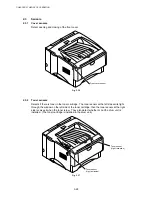
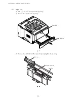
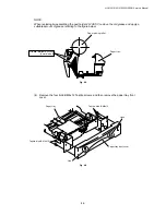
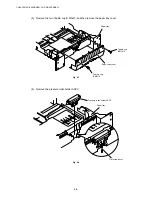
Страница 114: ...HL 5130 5140 5150D 5150DN Service Manual 4 13 24 Remove the paper rear guide Fig 4 20 Paper tray Paper rear guide 2 1 1 ...
Страница 271: ...APPENDIX A 9 Appendix 9 Engine PCB Circuit Diagram 1 2 NAME CODE B512153CIR 1 2 LJ923001 A 9 ...
Страница 272: ...APPENDIX A 10 Appendix 10 Engine PCB Circuit Diagram 2 2 NAME CODE B512153CIR 2 2 LJ923001 A 10 ...
Страница 273: ...APPENDIX A 11 Appendix 11 Low voltage Power Supply PCB Circuit Diagram 120V NAME Low voltage PS Circuit 120V A 11 ...
Страница 274: ...APPENDIX A 12 Appendix 12 Low voltage Power Supply PCB Circuit Diagram 230V NAME Low voltage PS Circuit 230V A 12 ...
Страница 275: ...APPENDIX A 13 Appendix 13 High voltage Power Supply PCB Circuit Diagram NAME High voltage PS Circuit A 13 ...


