


HL-5130/5140/5150D/5170DN SERVICE MANUAL
5-5
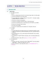
!
CAUTION:
*It is recommended to place the drum unit assembly on a piece of disposable paper or cloth in
case you accidentally spill or scatter toner.
*To prevent damage to the printer from static electricity, do not touch the electrodes shown in
the figure below.
Fig.5-9
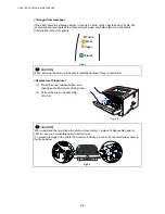
(3) Push down the blue lock lever and take
the toner cartridge out of the drum unit
assembly.
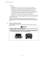
(4) Unpack the new toner cartridge. Hold
the cartridge level with both hands and
gently rock it from side to side five or six
times to spread the toner evenly inside
the cartridge. (Fig.5-10)
Fig. 5-10
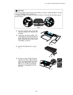
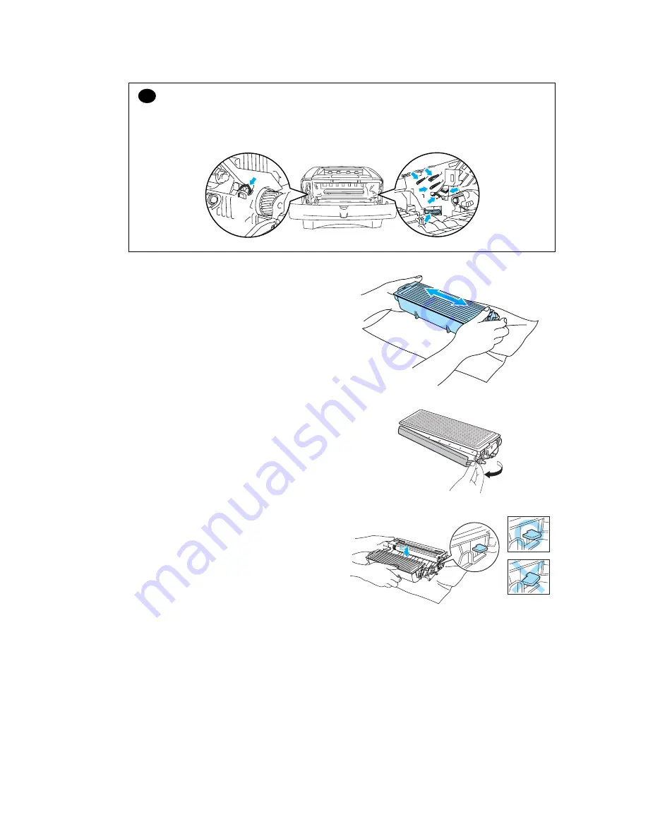
(5) Remove the protective cover. (Fig.5-
11)
Fig. 5-11
(6) Put the new toner cartridge firmly into
the drum unit until you hear it lock into
place. If you put it in properly, the lock
lever will lift automatically. (Fig.5-12)
Make sure you fit the toner cartridge
properly or it may separate from the
drum unit.
Fig. 5-12
Содержание HL-5130
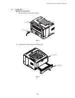
Страница 114: ...HL 5130 5140 5150D 5150DN Service Manual 4 13 24 Remove the paper rear guide Fig 4 20 Paper tray Paper rear guide 2 1 1 ...
Страница 271: ...APPENDIX A 9 Appendix 9 Engine PCB Circuit Diagram 1 2 NAME CODE B512153CIR 1 2 LJ923001 A 9 ...
Страница 272: ...APPENDIX A 10 Appendix 10 Engine PCB Circuit Diagram 2 2 NAME CODE B512153CIR 2 2 LJ923001 A 10 ...
Страница 273: ...APPENDIX A 11 Appendix 11 Low voltage Power Supply PCB Circuit Diagram 120V NAME Low voltage PS Circuit 120V A 11 ...
Страница 274: ...APPENDIX A 12 Appendix 12 Low voltage Power Supply PCB Circuit Diagram 230V NAME Low voltage PS Circuit 230V A 12 ...
Страница 275: ...APPENDIX A 13 Appendix 13 High voltage Power Supply PCB Circuit Diagram NAME High voltage PS Circuit A 13 ...


