


HL-5130/5140/5150D/5150DN Service Manual
4-55
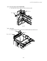
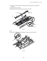
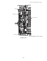
(26) Remove the hook of the bearing 5, and then slide the feed roller ASSY in the direction of
the arrow.
(27) Remove the feed roller ASSY.
(28) Remove the joint 5 and the bearing 5 from the feed roller ASSY.
Fig. 4-97
NOTE:
Be careful that the different direction installation causes jam when you install joint 5.
Fig. 4-98
Bearing 5
Joint 5
Feed roller ASSY
Hook
1
2
3
4
5
Bearing 5
Joint 5
Содержание HL-5130
Страница 114: ...HL 5130 5140 5150D 5150DN Service Manual 4 13 24 Remove the paper rear guide Fig 4 20 Paper tray Paper rear guide 2 1 1 ...
Страница 271: ...APPENDIX A 9 Appendix 9 Engine PCB Circuit Diagram 1 2 NAME CODE B512153CIR 1 2 LJ923001 A 9 ...
Страница 272: ...APPENDIX A 10 Appendix 10 Engine PCB Circuit Diagram 2 2 NAME CODE B512153CIR 2 2 LJ923001 A 10 ...
Страница 273: ...APPENDIX A 11 Appendix 11 Low voltage Power Supply PCB Circuit Diagram 120V NAME Low voltage PS Circuit 120V A 11 ...
Страница 274: ...APPENDIX A 12 Appendix 12 Low voltage Power Supply PCB Circuit Diagram 230V NAME Low voltage PS Circuit 230V A 12 ...
Страница 275: ...APPENDIX A 13 Appendix 13 High voltage Power Supply PCB Circuit Diagram NAME High voltage PS Circuit A 13 ...


