


CHAPTER 3 THEORY OF OPERATION
3-18
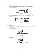
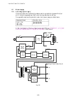
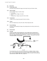
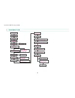
1.5 Power
Supply
1.5.1
Low-voltage power supply
The power supply uses a switching regulation system to generate the regulated DC power
(+3.3V, +8V [non regulated] and +24V), which are converted from the AC line.
The regulated output and the production code of each power supply are listed below;
Regulated Output
Production Code
+3.3V / 1.5A
+8V / 0.4A
+24V / 2.2A
100V: MPW5806
200V: MPW5706
For the circuit diagram of the low-voltage power supply PCB, see
APPENDIX 11. or 12. ‘LOW-
VOLTAGE POWER SUPPLY PCB CIRCUIT DIAGRAM’
in this manual.
Heater
Circuit
Thermal
Fuse
Feedback
Line
Filter
Fuse
Rectifier
Oscillator
24V
Regulation
Circuit
24V
3.3V
Lamp
(Heater)
(Engin Circuit / Main Circuit)
3.3V
Regulation
Circuit
Lightning
Surge
Absorber
Fuse
8V
Fig. 3-29
Содержание HL-5130
Страница 114: ...HL 5130 5140 5150D 5150DN Service Manual 4 13 24 Remove the paper rear guide Fig 4 20 Paper tray Paper rear guide 2 1 1 ...
Страница 271: ...APPENDIX A 9 Appendix 9 Engine PCB Circuit Diagram 1 2 NAME CODE B512153CIR 1 2 LJ923001 A 9 ...
Страница 272: ...APPENDIX A 10 Appendix 10 Engine PCB Circuit Diagram 2 2 NAME CODE B512153CIR 2 2 LJ923001 A 10 ...
Страница 273: ...APPENDIX A 11 Appendix 11 Low voltage Power Supply PCB Circuit Diagram 120V NAME Low voltage PS Circuit 120V A 11 ...
Страница 274: ...APPENDIX A 12 Appendix 12 Low voltage Power Supply PCB Circuit Diagram 230V NAME Low voltage PS Circuit 230V A 12 ...
Страница 275: ...APPENDIX A 13 Appendix 13 High voltage Power Supply PCB Circuit Diagram NAME High voltage PS Circuit A 13 ...


