


HL-5130/5140/5150D/5150DN Service Manual
4-47
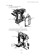
3.20 Engine
PCB
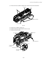
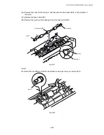
(1) Disconnect the connectors.
Fig. 4-82
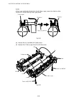
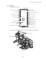
(2) Remove the two bind B M4x12 Taptite screws, and then remove the engine PCB ASSY.
Fig. 4-83
Taptite, bind B M4x12
Engine PCB ASSY
Engine PCB ASSY
Toner sensor
(light reception) connector
Thermistor relay PCB connector
Main motor connector
Main PCB connector
MP tray PCB connector
FR solenoid connector
PF solenoid connector
Fan motor 60 unit connector
LT connector
Polygon motor connector
Fan motor 60 connector
LVPS connector
Cassette sensor PCB connector
Toner sensor
(light emission) connector
HVPS connector
DX rear cover connector
DX solenoid connector
DX sensor PCB connector
Содержание HL-5130
Страница 114: ...HL 5130 5140 5150D 5150DN Service Manual 4 13 24 Remove the paper rear guide Fig 4 20 Paper tray Paper rear guide 2 1 1 ...
Страница 271: ...APPENDIX A 9 Appendix 9 Engine PCB Circuit Diagram 1 2 NAME CODE B512153CIR 1 2 LJ923001 A 9 ...
Страница 272: ...APPENDIX A 10 Appendix 10 Engine PCB Circuit Diagram 2 2 NAME CODE B512153CIR 2 2 LJ923001 A 10 ...
Страница 273: ...APPENDIX A 11 Appendix 11 Low voltage Power Supply PCB Circuit Diagram 120V NAME Low voltage PS Circuit 120V A 11 ...
Страница 274: ...APPENDIX A 12 Appendix 12 Low voltage Power Supply PCB Circuit Diagram 230V NAME Low voltage PS Circuit 230V A 12 ...
Страница 275: ...APPENDIX A 13 Appendix 13 High voltage Power Supply PCB Circuit Diagram NAME High voltage PS Circuit A 13 ...


