


CHAPTER 4 DISASSEMBLY AND RE-ASSEMBLY
4-60
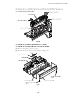
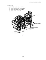
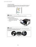
(13) Remove the four cup S M3x6 Taptite screws, and then remove the main motor ASSY.
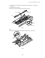
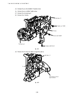
(14) Remove the develop joint and joint spring from the drive unit.
(15) Release the two hooks from the develop joint, and remove the joint stopper.
Fig. 4-105
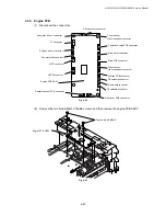
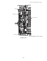
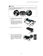
(16) Remove the gear 40/54Y, gear 17 planetary, gear 45 arm F/R, and gear 20 center F/R
from the main frame L.
Fig. 4-106
Taptite, cup S M3x6
Main motor ASSY
Drive unit
Taptite, cup S M3x6
Joint spring
Gear 40/54Y
Gear 17
planetary
Gear 45
arm F/R
Gear 20
center F/R
Joint stopper
Develop joint
Содержание HL-5130
Страница 114: ...HL 5130 5140 5150D 5150DN Service Manual 4 13 24 Remove the paper rear guide Fig 4 20 Paper tray Paper rear guide 2 1 1 ...
Страница 271: ...APPENDIX A 9 Appendix 9 Engine PCB Circuit Diagram 1 2 NAME CODE B512153CIR 1 2 LJ923001 A 9 ...
Страница 272: ...APPENDIX A 10 Appendix 10 Engine PCB Circuit Diagram 2 2 NAME CODE B512153CIR 2 2 LJ923001 A 10 ...
Страница 273: ...APPENDIX A 11 Appendix 11 Low voltage Power Supply PCB Circuit Diagram 120V NAME Low voltage PS Circuit 120V A 11 ...
Страница 274: ...APPENDIX A 12 Appendix 12 Low voltage Power Supply PCB Circuit Diagram 230V NAME Low voltage PS Circuit 230V A 12 ...
Страница 275: ...APPENDIX A 13 Appendix 13 High voltage Power Supply PCB Circuit Diagram NAME High voltage PS Circuit A 13 ...


