


HL-5130/5140/5150D/5150DN Service Manual
4-15
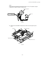
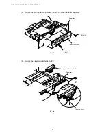
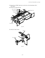
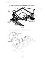
NOTE:
Set pressure roller, and assemble pressure roller spring after assembling DX roller holder.
Fig. 4-23
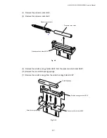
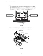
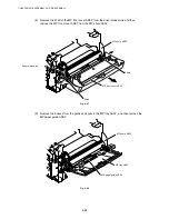
(4) Remove the two bind B M3x8 Taptite screws, and then remove the guide plate stopper.
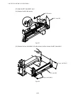
(5) Remove the two left guide spring 2.
Fig. 4-24
Left guide spring 2
Taptite, bind B M3x8
Taptite, bind B M3x8
Guide plate stopper
Guide plate stoller
Left guide spring 2
Left guide spring 2
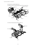
Tray feed ZL2
Tray feed ZL2
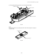
Pressure roller
Pressure roller spring
Содержание HL-5130
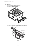
Страница 114: ...HL 5130 5140 5150D 5150DN Service Manual 4 13 24 Remove the paper rear guide Fig 4 20 Paper tray Paper rear guide 2 1 1 ...
Страница 271: ...APPENDIX A 9 Appendix 9 Engine PCB Circuit Diagram 1 2 NAME CODE B512153CIR 1 2 LJ923001 A 9 ...
Страница 272: ...APPENDIX A 10 Appendix 10 Engine PCB Circuit Diagram 2 2 NAME CODE B512153CIR 2 2 LJ923001 A 10 ...
Страница 273: ...APPENDIX A 11 Appendix 11 Low voltage Power Supply PCB Circuit Diagram 120V NAME Low voltage PS Circuit 120V A 11 ...
Страница 274: ...APPENDIX A 12 Appendix 12 Low voltage Power Supply PCB Circuit Diagram 230V NAME Low voltage PS Circuit 230V A 12 ...
Страница 275: ...APPENDIX A 13 Appendix 13 High voltage Power Supply PCB Circuit Diagram NAME High voltage PS Circuit A 13 ...