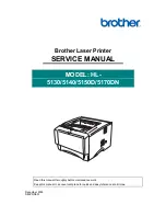
HL-5130/5140/5150D/5170DN SERVICE MANUAL
v
3.21 High-voltage PS PCB ASSY .......................................................................................... 4-48
3.22 Low-voltage PS PCB ASSY........................................................................................... 4-48
3.23 Paper Feeder ................................................................................................................. 4-50
3.24 Frame L/ Drive Unit ........................................................................................................ 4-58
3.25 Fan Motor 60 Unit LV/ Fan Motor 60 Unit...................................................................... 4-62
3.26 Frame R ......................................................................................................................... 4-63
4. PACKING ................................................................................................................ 4-65
5. LUBRICATION ........................................................................................................ 4-66
6
. GUIDELINES FOR LEAD FREE SOLDER.............................................................. 4-68
CHAPTER 5 PERIODIC MAINTENANCE............................................... 5-1
1. CONSUMABLE
PARTS............................................................................................. 5-1
1.1 Drum Unit ......................................................................................................................... 5-1
1.2 Toner
Cartridge ................................................................................................................ 5-3
2. PERIODICAL
REPLACEMENT PARTS .................................................................... 5-8
2.1 Fixing Unit......................................................................................................................... 5-9
2.2 Paper Feeding Kit........................................................................................................... 5-12
3. PERIODICAL
CLEANING........................................................................................ 5-14
3.1 Cleaning the Printer Exterior.......................................................................................... 5-14
3.2 Cleaning the Drum Unit.................................................................................................. 5-14
3.3 Cleaning the Scanner Window ...................................................................................... 5-15
3.4 Cleaning the Electrical Terminals .................................................................................. 5-16
4. MTBF / MTTR .......................................................................................................... 5-17
CHAPTER 6 TROUBLESHOOTING ....................................................... 6-1
1. INTRODUCTION ....................................................................................................... 6-1
1.1 Initial Check...................................................................................................................... 6-1
1.2 Warnings for Maintenance Work ..................................................................................... 6-2
1.3 Identify
the Problem ......................................................................................................... 6-3
2. OPERATOR CALLS & SERVICE CALLS.................................................................. 6-4
2.1 Operator Calls .................................................................................................................. 6-4
2.2 Service Calls .................................................................................................................... 6-5
3. ERROR
MESSAGE ................................................................................................... 6-6
3.1 Error Message in the Status Monitor ............................................................................... 6-6
3.2 Error
Message
Printouts .................................................................................................. 6-7
4. PAPER
PROBLEMS.................................................................................................. 6-8
4.1 Paper
Loading
Problems ................................................................................................. 6-8
4.2 Paper Jams ...................................................................................................................... 6-9
4.2.1 Clearing jammed paper ....................................................................................................... 6-9
4.2.2 Causes & countermeasures .............................................................................................. 6-13
4.3 Paper
Feeding
Problems ............................................................................................... 6-14
5. SOFTWARE
SETTING PROBLEMS....................................................................... 6-16
6. MALFUNCTIONS .................................................................................................... 6-19
7. IMAGE
DEFECTS ................................................................................................... 6-24
Содержание HL-5130
Страница 114: ...HL 5130 5140 5150D 5150DN Service Manual 4 13 24 Remove the paper rear guide Fig 4 20 Paper tray Paper rear guide 2 1 1 ...
Страница 271: ...APPENDIX A 9 Appendix 9 Engine PCB Circuit Diagram 1 2 NAME CODE B512153CIR 1 2 LJ923001 A 9 ...
Страница 272: ...APPENDIX A 10 Appendix 10 Engine PCB Circuit Diagram 2 2 NAME CODE B512153CIR 2 2 LJ923001 A 10 ...
Страница 273: ...APPENDIX A 11 Appendix 11 Low voltage Power Supply PCB Circuit Diagram 120V NAME Low voltage PS Circuit 120V A 11 ...
Страница 274: ...APPENDIX A 12 Appendix 12 Low voltage Power Supply PCB Circuit Diagram 230V NAME Low voltage PS Circuit 230V A 12 ...
Страница 275: ...APPENDIX A 13 Appendix 13 High voltage Power Supply PCB Circuit Diagram NAME High voltage PS Circuit A 13 ...

