


CHAPTER 4 DISASSEMBLY AND RE-ASSEMBLY
4-38
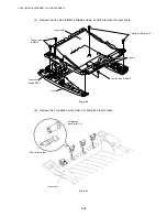
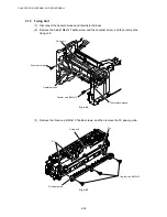
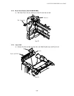
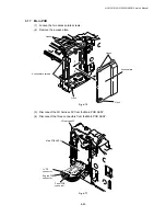
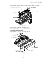
(19) Remove the three cleaner spring S.
(20) Remove the three cleaner pinch roller ASSY S.
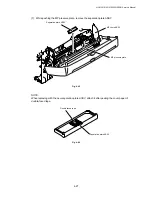
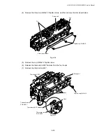
(21) Remove the cleaner spring L.
(22) Remove the cleaner pinch roller ASSY L.
Fig. 4-66
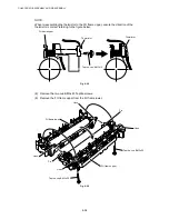
NOTE:
•
When re-assembling the cleaner pinch roller ASSY complete with the cleaner spring onto
the FU frame lower, ensure the direction of the roller is correct referring to the figure above.
•
Ensure that the both springs are seated correctly in the locating channel and does not
protrude from either end.
•
Ensure also that the proper spring is fixed to the each cleaner pinch roller ASSY because
the both springs are NOT identical with each other.
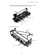
Fig. 4-67
FU frame lower
Cleaner pinch roller ASSY S
Cleaner pinch roller ASSY S
Cleaner pinch roller ASSY L
Cleaner spring S
Cleaner spring
FU frame lower
Cleaner pinch roller ASSY
Cleaner spring S
Cleaner spring L
Содержание HL-5130
Страница 114: ...HL 5130 5140 5150D 5150DN Service Manual 4 13 24 Remove the paper rear guide Fig 4 20 Paper tray Paper rear guide 2 1 1 ...
Страница 271: ...APPENDIX A 9 Appendix 9 Engine PCB Circuit Diagram 1 2 NAME CODE B512153CIR 1 2 LJ923001 A 9 ...
Страница 272: ...APPENDIX A 10 Appendix 10 Engine PCB Circuit Diagram 2 2 NAME CODE B512153CIR 2 2 LJ923001 A 10 ...
Страница 273: ...APPENDIX A 11 Appendix 11 Low voltage Power Supply PCB Circuit Diagram 120V NAME Low voltage PS Circuit 120V A 11 ...
Страница 274: ...APPENDIX A 12 Appendix 12 Low voltage Power Supply PCB Circuit Diagram 230V NAME Low voltage PS Circuit 230V A 12 ...
Страница 275: ...APPENDIX A 13 Appendix 13 High voltage Power Supply PCB Circuit Diagram NAME High voltage PS Circuit A 13 ...


