


CHAPTER 7 SOFTWARE SERVICE SUPPORT
7-4
<HL-5140>
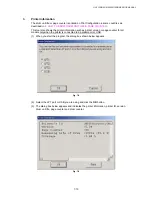
After checking of all 6 sensors, Toner LED is lit if no unusual states are detected.
*
Front registration sensor
*
Rear registration sensor
*
Paper eject sensor
*
Front cover sensor
*
Fixing unit cover sensor
* Toner
sensor
After checking of all 5 sensors, Drum LED is lit if no unusual states are detected.
*
Tray 1 paper loading sensor
*
Tray 1 cassette sensor
*
Tray 2 paper loading sensor
*
Tray 2 cassette sensor
*
Tray 2 registration sensor
<HL-5150D/5170DN>
After checking of all 6 sensors, Toner LED is lit if no unusual states are detected.
*
Front registration sensor
*
Rear registration sensor
*
Paper eject sensor
*
Front cover sensor
*
Fixing unit cover sensor
* Toner
sensor
After checking of all 6 sensors, Drum LED is lit if no unusual states are detected.
*
Tray 1 paper loading sensor
*
Tray 1 cassette sensor
*
MP paper loading sensor
*
Tray 2 paper loading sensor
*
Tray 2 cassette sensor
*
Tray 2 registration sensor
After checking of all 3 sensors, Paper LED is lit if no unusual states are detected.
*
Duplex printing lever sensor
*
Duplex printing tray sensor
*
Duplex printing rear cover sensor
Содержание HL-5130
Страница 114: ...HL 5130 5140 5150D 5150DN Service Manual 4 13 24 Remove the paper rear guide Fig 4 20 Paper tray Paper rear guide 2 1 1 ...
Страница 271: ...APPENDIX A 9 Appendix 9 Engine PCB Circuit Diagram 1 2 NAME CODE B512153CIR 1 2 LJ923001 A 9 ...
Страница 272: ...APPENDIX A 10 Appendix 10 Engine PCB Circuit Diagram 2 2 NAME CODE B512153CIR 2 2 LJ923001 A 10 ...
Страница 273: ...APPENDIX A 11 Appendix 11 Low voltage Power Supply PCB Circuit Diagram 120V NAME Low voltage PS Circuit 120V A 11 ...
Страница 274: ...APPENDIX A 12 Appendix 12 Low voltage Power Supply PCB Circuit Diagram 230V NAME Low voltage PS Circuit 230V A 12 ...
Страница 275: ...APPENDIX A 13 Appendix 13 High voltage Power Supply PCB Circuit Diagram NAME High voltage PS Circuit A 13 ...


