


HL-5130/5140/5150D/5170DN SERVICE MANUAL
2-1
CHAPTER 2 INSTALLATION AND BASIC OPERATION
1. CONDITIONS REQUIRED FOR INSTALLATION
1.1 Power
Supply
•
The source voltage must stay within ±10% of the rated voltage shown on the rating plate.
•
The power cord, including extensions, should not exceed 5 meters (16.5 feet).
•
Do not share the same power circuit with other high-power appliances, particularly an air
conditioner, copier or shredder. If it is unavoidable that you must use the printer with these
appliances, it is recommended that you use an isolation transformer or a high-frequency
noise filter.
•
Use a voltage regulator if the power source is not stable.
1.2 Environment
•
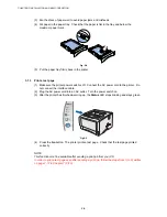
The printer should be installed near a power outlet, which is easily accessible.
•
The room temperature is maintained between 10°C and 32.5°C. The relative humidity is
maintained between 20% and 80%.
•
The printer should be used in a well ventilated room.
•
Place the printer on a flat, horizontal surface.
•
Keep the printer clean. Do not place the printer in a dusty place.
•
Do not place the printer where the ventilation hole of the printer is blocked. Keep
approximately 100 mm (4 inches) between the ventilation hole and the wall.
•
Do not place the printer where it is exposed to direct sunlight. Use a blind or a heavy
curtain to protect the printer from direct sunlight when the printer is unavoidably set up near
a window.
•
Do not place the printer near devices that contain magnets or generate magnetic fields.
•
Do not subject the printer to strong physical shocks or vibrations.
•
Do not expose the printer to open flames or salty or corrosive gasses.
•
Do not place objects on top of the printer.
•
Do not place the printer near an air conditioner.
•
Keep the printer horizontal when carrying.
•
Do not cover the slots in the side cover.
Содержание HL-5130
Страница 114: ...HL 5130 5140 5150D 5150DN Service Manual 4 13 24 Remove the paper rear guide Fig 4 20 Paper tray Paper rear guide 2 1 1 ...
Страница 271: ...APPENDIX A 9 Appendix 9 Engine PCB Circuit Diagram 1 2 NAME CODE B512153CIR 1 2 LJ923001 A 9 ...
Страница 272: ...APPENDIX A 10 Appendix 10 Engine PCB Circuit Diagram 2 2 NAME CODE B512153CIR 2 2 LJ923001 A 10 ...
Страница 273: ...APPENDIX A 11 Appendix 11 Low voltage Power Supply PCB Circuit Diagram 120V NAME Low voltage PS Circuit 120V A 11 ...
Страница 274: ...APPENDIX A 12 Appendix 12 Low voltage Power Supply PCB Circuit Diagram 230V NAME Low voltage PS Circuit 230V A 12 ...
Страница 275: ...APPENDIX A 13 Appendix 13 High voltage Power Supply PCB Circuit Diagram NAME High voltage PS Circuit A 13 ...


