


HL-5130/5140/5150D/5170DN SERVICE MANUAL
7-17
1.
Controller Firmware
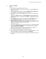
Writing procedure (For AVA file)
1) Choose Start…>Program…>Accessory…>Command prompt
Since the DOS window is opened, move the ZL2E folder.
Type c:+
ENTER
, CD \ZL2E +
ENTER
.
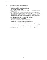
2) Turn off the printer. Connect the USB cable to the printer. Open the front cover, and turn
on the printer while holding down the
Go
button. When the printer enters into the
inspection mode, the
Toner
LED is ON. Release the
Go
button. Holding down the
Go
button will cause the LEDs to turn ON in the order Toner
→
Drum
→
Paper
→
Status
→
Toner + Drum
→
Drum + Paper
→
Paper + Status. Release the Go button when the
Toner
and
Drum
LEDs light up.
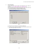
3) Type “Batch file” name and “AVA file” name, then press
ENTER
key.
Example) FW5170DN LZ0011_A.AVA +
ENTER
Data is sent to the printer via the USB cable, and start writing.
(While the data is sent to the printer;
Status
LED (orange) blinking.)
(While writing the firmware;
Status
LED (red) blinking)
Even if the batch file is completed, the data is still transmitted or the writing procedure
continues. So, be sure
NOT
to shut down the Windows system, turn the printer off, unplug
the cable and turn the PC off until all the LEDs light up. Re-writing may be impossible if
writing procedure goes wrong.
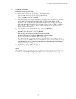
4) After finishing writing, all the LEDs light up.
NOTE;
Plug and Play will run automatically when the printer is rebooted, then the printer driver (copy
2) will be created. (START>Setting>Printer) Delete the created printer driver (copy 2).
Содержание HL-5130
Страница 114: ...HL 5130 5140 5150D 5150DN Service Manual 4 13 24 Remove the paper rear guide Fig 4 20 Paper tray Paper rear guide 2 1 1 ...
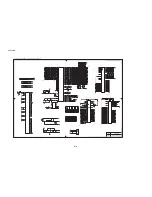
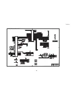
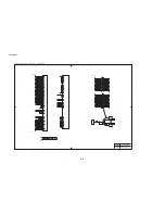
Страница 271: ...APPENDIX A 9 Appendix 9 Engine PCB Circuit Diagram 1 2 NAME CODE B512153CIR 1 2 LJ923001 A 9 ...
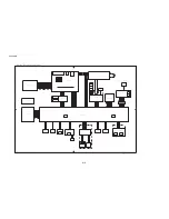
Страница 272: ...APPENDIX A 10 Appendix 10 Engine PCB Circuit Diagram 2 2 NAME CODE B512153CIR 2 2 LJ923001 A 10 ...
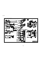
Страница 273: ...APPENDIX A 11 Appendix 11 Low voltage Power Supply PCB Circuit Diagram 120V NAME Low voltage PS Circuit 120V A 11 ...
Страница 274: ...APPENDIX A 12 Appendix 12 Low voltage Power Supply PCB Circuit Diagram 230V NAME Low voltage PS Circuit 230V A 12 ...
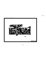
Страница 275: ...APPENDIX A 13 Appendix 13 High voltage Power Supply PCB Circuit Diagram NAME High voltage PS Circuit A 13 ...


