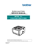
HL-5130/5140/5150D/5170DN SERVICE MANUAL
iii
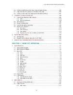
4.6 Printing on Both Sides of the Paper (manual duplex printing)....................................... 2-24
4.7 Paper orientation for printing on both sides of the paper............................................... 2-26
4.8 Printing on both sides of the paper (automatic duplex printing) .................................... 2-27
5. CONTROL PANEL OPERATION ............................................................................ 2-28
5.1 Control Panel Buttons & LED functions ......................................................................... 2-28
5.1.1 LEDs ................................................................................................................................. 2-28
5.1.2 Control
Panel Buttons ....................................................................................................... 2-28
5.2 LED
Indiations................................................................................................................ 2-29
5.3 Service
call indications................................................................................................... 2-31
5.4 Control Panel Button Operations ................................................................................... 2-32
5.5 Other
Control Features .................................................................................................. 2-33
5.5.1 Sleep mode ....................................................................................................................... 2-33
5.5.2 Print
a test page ................................................................................................................ 2-34
5.5.3 Print Settings..................................................................................................................... 2-34
5.5.4 Print fonts (For HL-5140, HL-5150D and HL-5170DN) ..................................................... 2-35
6. NETWORK
FUNCTIONS ........................................................................................ 2-36
6.1 LED
functions................................................................................................................. 2-36
6.2 Network Factory default setting (For HL-5170DN) ........................................................ 2-36
7. PAPER TRAY INFORMATION (FOR EUROPE ONLY) .......................................... 2-37
CHAPTER 3 THEORY OF OPERATION ................................................ 3-1
1. ELECTRONICS ......................................................................................................... 3-1
1.1 General
Block Diagram.................................................................................................... 3-1
1.2 Main PCB Block Diagram ................................................................................................ 3-2
1.3 Main PCB ......................................................................................................................... 3-3
1.3.1 CPU .................................................................................................................................... 3-3
1.3.2 USB..................................................................................................................................... 3-5
1.3.3 IEEE 1284........................................................................................................................... 3-6
1.3.4 Network
Interface ................................................................................................................ 3-7
1.3.5 ROM.................................................................................................................................... 3-8
1.3.6 Flash ROM.......................................................................................................................... 3-9
1.3.7 SDRAM ............................................................................................................................. 3-10
1.3.8 Optional RAM.................................................................................................................... 3-11
1.3.9 EEPROM .......................................................................................................................... 3-13
1.3.10 Reset Circuit ..................................................................................................................... 3-13
1.3.11 Engine I/O ......................................................................................................................... 3-14
1.3.12 Panel I/O ........................................................................................................................... 3-14
1.3.13 Video I/O ........................................................................................................................... 3-15
1.3.14 Power Supply .................................................................................................................... 3-16
1.4 Engine PCB.................................................................................................................... 3-17
1.5 Power
Supply ................................................................................................................. 3-18
1.5.1 Low-voltage
Power Supply ................................................................................................ 3-18
1.5.2 High-voltage
Power Supply ............................................................................................... 3-19
2. MECHANICS ........................................................................................................... 3-20
2.1 Overview of Printing Mechanism ................................................................................... 3-20
2.2 Paper
Transfer ............................................................................................................... 3-21
2.2.1 Paper supply ..................................................................................................................... 3-21
Содержание HL-5130
Страница 114: ...HL 5130 5140 5150D 5150DN Service Manual 4 13 24 Remove the paper rear guide Fig 4 20 Paper tray Paper rear guide 2 1 1 ...
Страница 271: ...APPENDIX A 9 Appendix 9 Engine PCB Circuit Diagram 1 2 NAME CODE B512153CIR 1 2 LJ923001 A 9 ...
Страница 272: ...APPENDIX A 10 Appendix 10 Engine PCB Circuit Diagram 2 2 NAME CODE B512153CIR 2 2 LJ923001 A 10 ...
Страница 273: ...APPENDIX A 11 Appendix 11 Low voltage Power Supply PCB Circuit Diagram 120V NAME Low voltage PS Circuit 120V A 11 ...
Страница 274: ...APPENDIX A 12 Appendix 12 Low voltage Power Supply PCB Circuit Diagram 230V NAME Low voltage PS Circuit 230V A 12 ...
Страница 275: ...APPENDIX A 13 Appendix 13 High voltage Power Supply PCB Circuit Diagram NAME High voltage PS Circuit A 13 ...

