


CHAPTER 2 INSTALLATION AND BASIC OPERATION
2-36
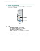
6. NETWORK FUNCTIONS (FOR HL-5170DN)
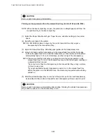
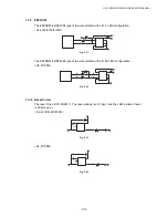
6.1 LED
functions
Fig. 2-47
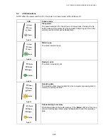
No light:
If both of the two LEDs are off, then the print server is not connected to the network.
Link/Speed LED is orange: Fast Ethernet
Link/Speed LED is green: 10 Base T Ethernet
This Link/Speed LED will be orange if the print server is connected to a 100BaseTX Fast
Ethernet network.
This Link/Speed LED will be green if the print server is connected to a 10 Base T Ethernet.
Active LED is yellow:
The Active LED will blink if the print server is receiving or transmitting data.
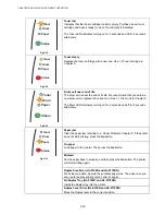
6.2
Network Factory default setting (For HL-5170DN)
If you wish to reset the print server back to its default settings (resetting all information such
as the password and IP address information), please follow these steps;
(1) Turn off the printer.
(2) Make sure that the front cover is closed and the power cord is plugged in.
(3) Hold down the Go button as you turn on the power switch. All the LEDs will light up. Keep
the Go button pressed down until all the LEDs except for Toner LED go off. When the
Drum, Paper and Status LEDs go off, release the Go button.
(4) Hold down the Go button and keep it pressed down until the yellow Status LED comes on.
When the Status LED comes on, release the Go button.
(5) When all the LEDs light up again, the printer will start warming up. The print server has
been reset to its default factory settings.
NOTE:
*If you wish to reset the printer and automatically disable the APIPA protocol, follow steps 1 to
4 above, however, hold down the Go button until the Status LED is green, not yellow.
*For more information on APIPA, see the Network User’s Guide or visit
http://solutions.brother.com
Link/Speed LED
Active LED
Содержание HL-5130
Страница 114: ...HL 5130 5140 5150D 5150DN Service Manual 4 13 24 Remove the paper rear guide Fig 4 20 Paper tray Paper rear guide 2 1 1 ...
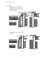
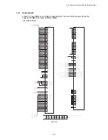
Страница 271: ...APPENDIX A 9 Appendix 9 Engine PCB Circuit Diagram 1 2 NAME CODE B512153CIR 1 2 LJ923001 A 9 ...
Страница 272: ...APPENDIX A 10 Appendix 10 Engine PCB Circuit Diagram 2 2 NAME CODE B512153CIR 2 2 LJ923001 A 10 ...
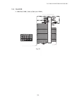
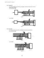
Страница 273: ...APPENDIX A 11 Appendix 11 Low voltage Power Supply PCB Circuit Diagram 120V NAME Low voltage PS Circuit 120V A 11 ...
Страница 274: ...APPENDIX A 12 Appendix 12 Low voltage Power Supply PCB Circuit Diagram 230V NAME Low voltage PS Circuit 230V A 12 ...
Страница 275: ...APPENDIX A 13 Appendix 13 High voltage Power Supply PCB Circuit Diagram NAME High voltage PS Circuit A 13 ...


