


HL-5130/5140/5150D/5170DN SERVICE MANUAL
5-3
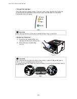
(3) While pressing the blue lock lever, take
the toner cartridge out of the drum unit
assembly. (Fig.5-4)
Fig. 5-4
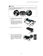
(4) Unpack the new drum unit.
(5) Put the toner cartridge in the new drum
unit until you hear it lock into place with
a click. When the toner cartridge is
installed correctly, the blue lock lever is
lifted automatically. (Fig.5-5) Make sure
you fit the toner cartridge properly, or it
may separate from the drum unit when
you pick up the drum unit assembly.
Fig. 5-5
(6) Put the drum unit assembly in the printer. Make sure that the printer is turned on, the
front cover is open and the
Status
LED is red.
(7) To reset the drum counter, press and hold down the
Go
button until all four LEDs are lit.
Once all four LEDs are lit, release the
Go
button.
(8) Close the front cover.
(9) Make sure that the
Drum
LED is now off.
!
CAUTION:
•
Only unpack a drum unit immediately before you need to install it into the printer. If an
unpacked drum unit is subjected to excessive direct sunlight or room light, the unit may be
damaged.
•
Handle the drum unit and toner cartridge carefully. If toner scatters on your hands or
clothes, wipe or wash it off with cold water immediately.
•
Discard the used drum unit according to local regulations, keeping it separate from
domestic waste. If you have questions, call your local waste disposal office.
•
Be sure to seal up the drum unit tightly so that toner powder does not spill out of the unit.
•
Do not reset the drum counter when replacing the toner cartridge only.
•
The
Drum
LED indication does not disappear until you reset the drum counter.
•
It is recommended to clean the printer when you replace the drum unit. Refer to
subsection 3. ‘PERIODICAL CLEANING’ in this Chapter
.
1.2 Toner
Cartridge
Life expectancy:
6,700 pages / high-yield toner cartridge
3,500 pages / standard cartridge
(When printing A4 or Letter size paper at 5% print coverage)
Содержание HL-5130
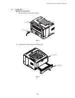
Страница 114: ...HL 5130 5140 5150D 5150DN Service Manual 4 13 24 Remove the paper rear guide Fig 4 20 Paper tray Paper rear guide 2 1 1 ...
Страница 271: ...APPENDIX A 9 Appendix 9 Engine PCB Circuit Diagram 1 2 NAME CODE B512153CIR 1 2 LJ923001 A 9 ...
Страница 272: ...APPENDIX A 10 Appendix 10 Engine PCB Circuit Diagram 2 2 NAME CODE B512153CIR 2 2 LJ923001 A 10 ...
Страница 273: ...APPENDIX A 11 Appendix 11 Low voltage Power Supply PCB Circuit Diagram 120V NAME Low voltage PS Circuit 120V A 11 ...
Страница 274: ...APPENDIX A 12 Appendix 12 Low voltage Power Supply PCB Circuit Diagram 230V NAME Low voltage PS Circuit 230V A 12 ...
Страница 275: ...APPENDIX A 13 Appendix 13 High voltage Power Supply PCB Circuit Diagram NAME High voltage PS Circuit A 13 ...


