


HL-5130/5140/5150D/5150DN Service Manual
4-7
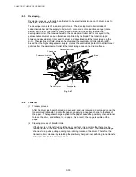
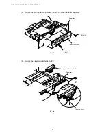
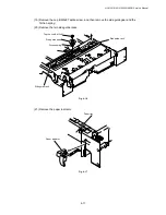
(7) Remove the pressure roller collar.
(8) Remove the pressure roller shaft.
Fig. 4-9
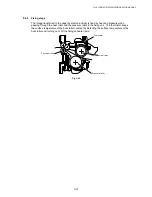
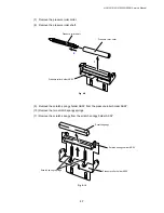
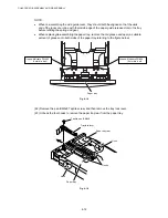
(9) Remove the scratch spongy holder ASSY from the pressure roller holder ASSY.
(10) Remove the two scratch spongy springs.
(11) Remove the scratch spongy from the scratch spongy holder ASSY.
Fig. 4-10
Pressure roller collar
Pressure roller shaft
Pressure roller holder ASSY
Scratch spongy
Scratch spongy holder ASSY
Pressure roller holder ASSY
Scratch spongy springs
1
2
Содержание HL-5130
Страница 114: ...HL 5130 5140 5150D 5150DN Service Manual 4 13 24 Remove the paper rear guide Fig 4 20 Paper tray Paper rear guide 2 1 1 ...
Страница 271: ...APPENDIX A 9 Appendix 9 Engine PCB Circuit Diagram 1 2 NAME CODE B512153CIR 1 2 LJ923001 A 9 ...
Страница 272: ...APPENDIX A 10 Appendix 10 Engine PCB Circuit Diagram 2 2 NAME CODE B512153CIR 2 2 LJ923001 A 10 ...
Страница 273: ...APPENDIX A 11 Appendix 11 Low voltage Power Supply PCB Circuit Diagram 120V NAME Low voltage PS Circuit 120V A 11 ...
Страница 274: ...APPENDIX A 12 Appendix 12 Low voltage Power Supply PCB Circuit Diagram 230V NAME Low voltage PS Circuit 230V A 12 ...
Страница 275: ...APPENDIX A 13 Appendix 13 High voltage Power Supply PCB Circuit Diagram NAME High voltage PS Circuit A 13 ...


