
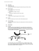


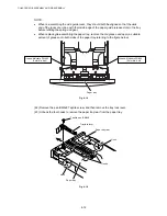


CHAPTER 4 DISASSEMBLY AND RE-ASSEMBLY
4-10
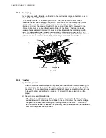
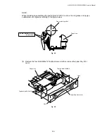
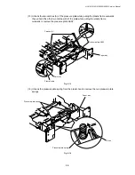
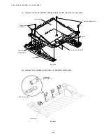
NOTE:
When re-assembling the pressure plate ASSY, ensure that the paper indicator arm is under
the pressure plate.
!
CAUTION:
When unhooking the catches to remove the pressure plate, do not bend the pressure plate,
gently ease the plastic cover. If the pressure plate is deformed, paper feeding problems may
occur.
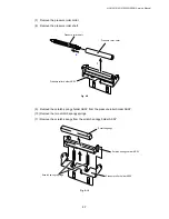
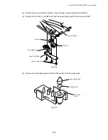
(17) Remove the herical extension spring.
(18) Remove the lock lever.
Fig. 4-15
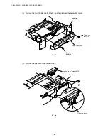
NOTE:
When re-assembling the lock lever, insert it upwards from underneath the paper tray and
rotate it until the two catches lock into place.
Herical extension spring
Lock lever
1
2
3
Paper tray
Paper tray
Lock lever
Содержание HL-5130
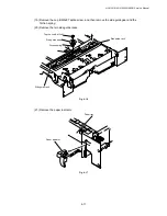
Страница 114: ...HL 5130 5140 5150D 5150DN Service Manual 4 13 24 Remove the paper rear guide Fig 4 20 Paper tray Paper rear guide 2 1 1 ...
Страница 271: ...APPENDIX A 9 Appendix 9 Engine PCB Circuit Diagram 1 2 NAME CODE B512153CIR 1 2 LJ923001 A 9 ...
Страница 272: ...APPENDIX A 10 Appendix 10 Engine PCB Circuit Diagram 2 2 NAME CODE B512153CIR 2 2 LJ923001 A 10 ...
Страница 273: ...APPENDIX A 11 Appendix 11 Low voltage Power Supply PCB Circuit Diagram 120V NAME Low voltage PS Circuit 120V A 11 ...
Страница 274: ...APPENDIX A 12 Appendix 12 Low voltage Power Supply PCB Circuit Diagram 230V NAME Low voltage PS Circuit 230V A 12 ...
Страница 275: ...APPENDIX A 13 Appendix 13 High voltage Power Supply PCB Circuit Diagram NAME High voltage PS Circuit A 13 ...


