


CHAPTER 4 DISASSEMBLY AND RE-ASSEMBLY
4-68
6. GUIDELINES FOR LEAD FREE SOLDER
All components are soldered using lead free solder, be sure to use
lead free solder
that
meets the following specification in the case of repair.
Lead free solder ; NIHON GENMA DHB-RMA3 NP303
(This can be distinguish from the lead free identification sign “LFH” on the MAIN PCB
ASSY REV.)
However, the solder side of the MAIN PCB ASSY and other PCBs are soldered using lead
content solder, use conventional lead content solder in the case of repair.
Since the reliability of soldering cannot be guaranteed if lead free solder and lead content
solder are mixed, take care not to use the incorrect solder or mix the solder types.
Information on Manually Repairing PCB Soldered with Lead-Free Solder
This document provides information on how to correctly make manual repairs to a printed circuit
board (PCB) soldered with lead-free solder.
1. Characteristics of lead-free solder
Melting point higher than that of conventional tin-lead solder
(Lead-free solder: approx. 220'C, Conventional tin-lead solder: approx. 180'C)
Relatively poor solder wettability and spread (difficult to wet and spread), and hard
Appearance (dull and grainy surface) different from that of conventional solder
Relatively poor wettability, rough surface (bumps are likely to be formed), and solder
dragging
Poor solder elevation
Poor thermal conductivity and heat resistant (difficult to melt)
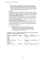
2. Metal composition & wire solder
The metal composition of lead-free solder allowed for use on PCBs for Brother's products is
following.
LF
Indication
Compositon
Manufacture
r
Origin Name
1
Sn/Ag/Cu
Nihon
Genma
Japan DHB-RMA3
NP303
H
only
Component-
side
Sn/Ag/Cu Nihon
Genma
Japan DHB-RMA3
NP303
We use wire solder which is indicated by digit after LF indication on PCB.
Wire solder made in the contries except Japan are under investigation,and will be evaluated.
3. Appearance quality criteria
The appearance of the surface of portions soldered with lead-free solder is basically the
same as that for those soldered with conventional lead-tin solder, except for the following
points.
1) The surface of a portion soldered with lead-free solder is dull and not smooth.
2) Shrinkage cracks can be observed on the surface of a portion soldered with lead-free
solder. (They can be observed using a magnifying glass with approx. 10x
magnification.)
Содержание HL-5130
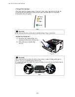
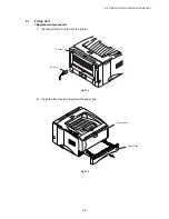
Страница 114: ...HL 5130 5140 5150D 5150DN Service Manual 4 13 24 Remove the paper rear guide Fig 4 20 Paper tray Paper rear guide 2 1 1 ...
Страница 271: ...APPENDIX A 9 Appendix 9 Engine PCB Circuit Diagram 1 2 NAME CODE B512153CIR 1 2 LJ923001 A 9 ...
Страница 272: ...APPENDIX A 10 Appendix 10 Engine PCB Circuit Diagram 2 2 NAME CODE B512153CIR 2 2 LJ923001 A 10 ...
Страница 273: ...APPENDIX A 11 Appendix 11 Low voltage Power Supply PCB Circuit Diagram 120V NAME Low voltage PS Circuit 120V A 11 ...
Страница 274: ...APPENDIX A 12 Appendix 12 Low voltage Power Supply PCB Circuit Diagram 230V NAME Low voltage PS Circuit 230V A 12 ...
Страница 275: ...APPENDIX A 13 Appendix 13 High voltage Power Supply PCB Circuit Diagram NAME High voltage PS Circuit A 13 ...


