


CHAPTER 4 DISASSEMBLY AND RE-ASSEMBLY
4-12
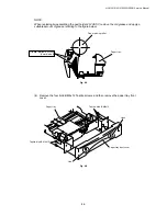
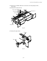
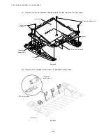
NOTE:
•
When re-assembling the side guide racks, they should both be aligned so that the wide
end of the racks are in line with the inside edge of the paper guide release slots in the tray
before refitting the spring and gear.
•
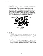
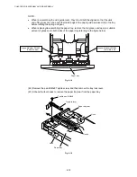
When replacing/re-assembling the paper tray, remove the old grease and apply a suitable
amount of grease onto both sides of the paper tray referring to the figure below;
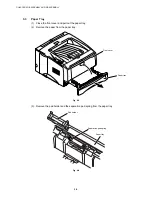
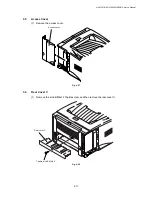
Fig. 4-18
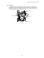
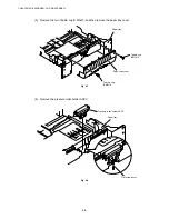
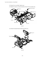
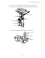
(22) Remove the pan B M3x8 Taptite screw, and then remove the tray lock lever.
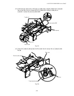
(23) Unhook the four hooks to remove the paper tray rear from the paper tray.
Fig. 4-19
Taptite, pan B M3x8
Tray lock lever
Paper tray
Hook
Paper tray rear
Paper tray
Grease: Molykote PG-662
(2 mm dia. ball)
Grease: Molykote PG-662
(2 mm dia. ball)
Hooks
Hook
Содержание HL-5130
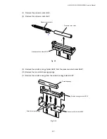
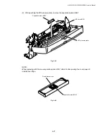
Страница 114: ...HL 5130 5140 5150D 5150DN Service Manual 4 13 24 Remove the paper rear guide Fig 4 20 Paper tray Paper rear guide 2 1 1 ...
Страница 271: ...APPENDIX A 9 Appendix 9 Engine PCB Circuit Diagram 1 2 NAME CODE B512153CIR 1 2 LJ923001 A 9 ...
Страница 272: ...APPENDIX A 10 Appendix 10 Engine PCB Circuit Diagram 2 2 NAME CODE B512153CIR 2 2 LJ923001 A 10 ...
Страница 273: ...APPENDIX A 11 Appendix 11 Low voltage Power Supply PCB Circuit Diagram 120V NAME Low voltage PS Circuit 120V A 11 ...
Страница 274: ...APPENDIX A 12 Appendix 12 Low voltage Power Supply PCB Circuit Diagram 230V NAME Low voltage PS Circuit 230V A 12 ...
Страница 275: ...APPENDIX A 13 Appendix 13 High voltage Power Supply PCB Circuit Diagram NAME High voltage PS Circuit A 13 ...


