


HL-5130/5140/5150D/5170DN SERVICE MANUAL
3-13
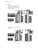
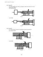
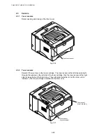
1.3.9 EEPROM
The EEPROM is BR24C04 type of two-wire method with a 512 x 8bit configuration.
<HL-5130/5140/5150D>
U2
BR24C04F
8
VCC
4
VSS
1
A0
2
A1
3
A2
5
SDA
7
TEST
6
SCL
R32
100
R31
100
0V
VDD3
0V
C31
C103
R30
4.7k
VDD3
TP58
TP59
TP67
TP68
EESCL
U5
Aurora
203
EESDA
202
Fig. 3-17
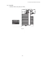
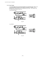
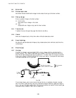
The EEPROM is BR24C64 type of two-wire method with a 8192 x 8bit configuration.
<HL-5170DN>
R77
100
R74
100
0V
VDD3
0V
C68
C103
R71
4.7k
VDD3
TP58
TP59
TP67
TP68
EESCL
203
U7
Aurora
EESDA
202
U6
M24C64-WMN6
8
VCC
4
VSS
1
A0
2
A1
3
A2
5
SDA
7
TEST
6
SCL
Fig. 3-18
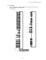
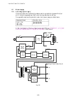
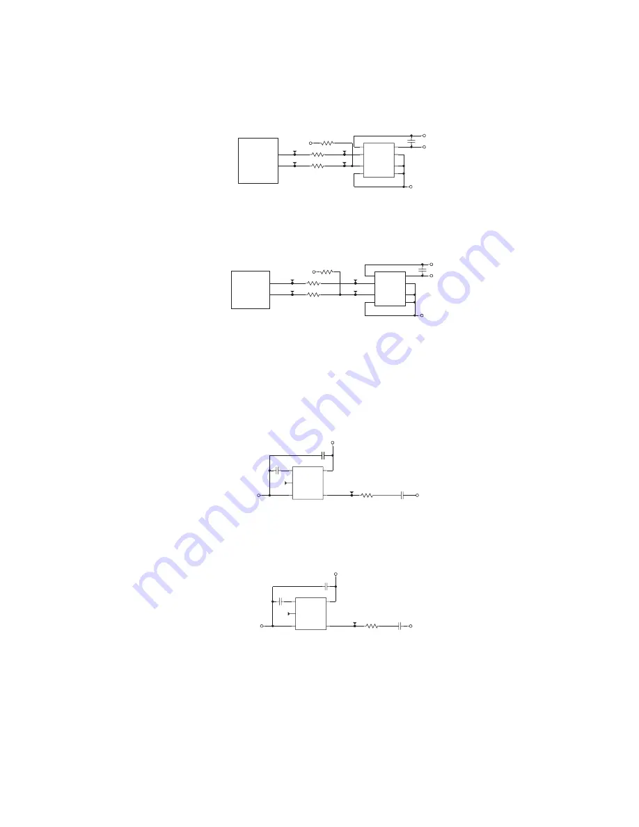
1.3.10 Reset
Circuit
The reset IC is a R3112N281C. The reset voltage is 2.8V (typ.) and the LOW period of reset
is 22.4ms (typ.)
< HL-5130/5140/5150D >
R43
68
C43
C101
0V
TP4
U3
R3112N281C
5
CD
2
VCC
1
VOUT
4
NC
3
GND
C40
C103
0V
VDD3
TP310
C33
C103
Fig. 3-19
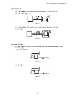
<HL-5170DN>
R84
68
C77
C101
0V
TP4
U5
R3112N281C
5
CD
2
VCC
1
VOUT
4
NC
3
GND
C75
C103
0V
VDD3
C71
C103
TP310
Fig. 3-20
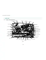
Содержание HL-5130
Страница 114: ...HL 5130 5140 5150D 5150DN Service Manual 4 13 24 Remove the paper rear guide Fig 4 20 Paper tray Paper rear guide 2 1 1 ...
Страница 271: ...APPENDIX A 9 Appendix 9 Engine PCB Circuit Diagram 1 2 NAME CODE B512153CIR 1 2 LJ923001 A 9 ...
Страница 272: ...APPENDIX A 10 Appendix 10 Engine PCB Circuit Diagram 2 2 NAME CODE B512153CIR 2 2 LJ923001 A 10 ...
Страница 273: ...APPENDIX A 11 Appendix 11 Low voltage Power Supply PCB Circuit Diagram 120V NAME Low voltage PS Circuit 120V A 11 ...
Страница 274: ...APPENDIX A 12 Appendix 12 Low voltage Power Supply PCB Circuit Diagram 230V NAME Low voltage PS Circuit 230V A 12 ...
Страница 275: ...APPENDIX A 13 Appendix 13 High voltage Power Supply PCB Circuit Diagram NAME High voltage PS Circuit A 13 ...


