


Page 4-62
MedPlus TotalAlert® Alarm Network Operation and Maintenance Manual (205728)
Remote-Mount Transducer
Chapter 4: Removal, Replacement, and Adjustment Procedures
4.23 Remote-Mount Transducer
Tools required:
Adjustable wrench
Phillips head screwdriver
Small screwdriver
Leak detection solution
Removal
WARNING:
Do not remove the threaded insert from the transducer. Doing so may
result in attaching the transducer to the incorrect gas or vacuum type,
endangering patient welfare.
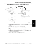
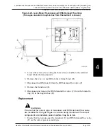
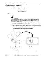
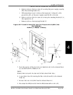
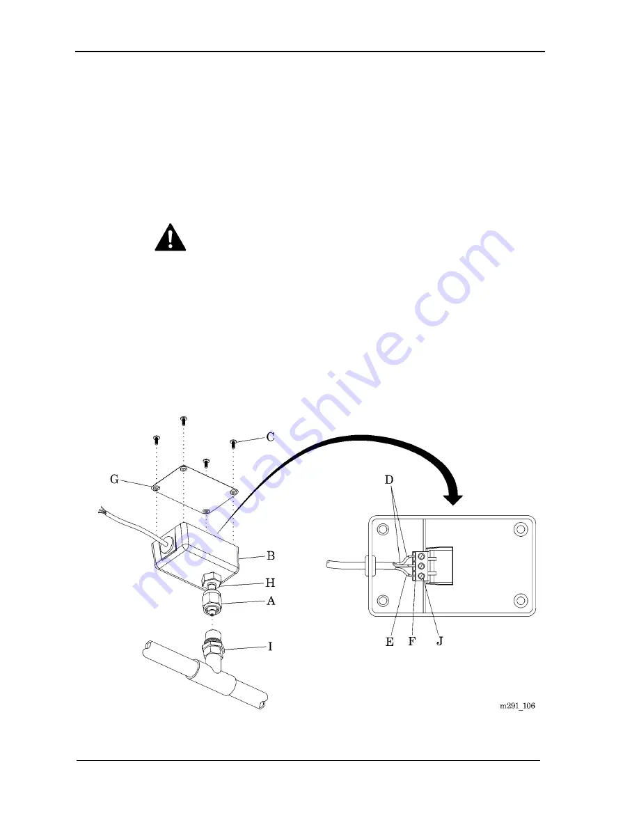
1. Leave the threaded insert (H) in the transducer (B). The transducer is not a
serviceable item (see figure 4-24 on page 4–62).
2. Using an adjustable wrench, remove the DISS nut (A) from the DISS demand
valve (I).
Figure 4-24. Remote-Mount Transducer Assembly
Содержание MedPlus TotalAlert
Страница 13: ...Page xii MedPlus TotalAlert Alarm Network Operation and Maintenance Manual 205728 Table of Contents NOTES...
Страница 17: ...Page 1 4 MedPlus TotalAlert Alarm Network Operation and Maintenance Manual 205728 Chapter 1 Introduction NOTES...
Страница 203: ...Page 3 2 MedPlus TotalAlert Alarm Network Operation and Maintenance Manual 205728 Chapter 3 Theory of Operation NOTES...
Страница 289: ...Page 5 2 MedPlus TotalAlert Alarm Network Operation and Maintenance Manual 205728 Chapter 5 Parts List NOTES...
Страница 367: ...Page 7 2 MedPlus TotalAlert Alarm Network Operation and Maintenance Manual 205728 Chapter 7 Accessories NOTES...
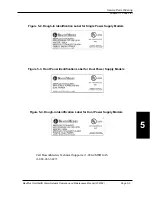
Страница 370: ...Schematic Wiring Diagram Typical Local Alarm...
Страница 371: ...Schematic Wiring Diagram Typical Master Alarm...
Страница 372: ...Schematic Wiring Diagram Typical Master Alarm to Master Alarm...
Страница 373: ...Schematic Wiring Diagram Typical Area Alarm...
Страница 374: ...Schematic Wiring Diagram Typical Master Alarm to Three Area Alarm...
Страница 375: ...Schematic Wiring Diagram Typical Master Alarm to Six Area Alarm Combination...


