


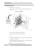
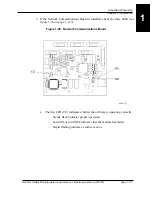


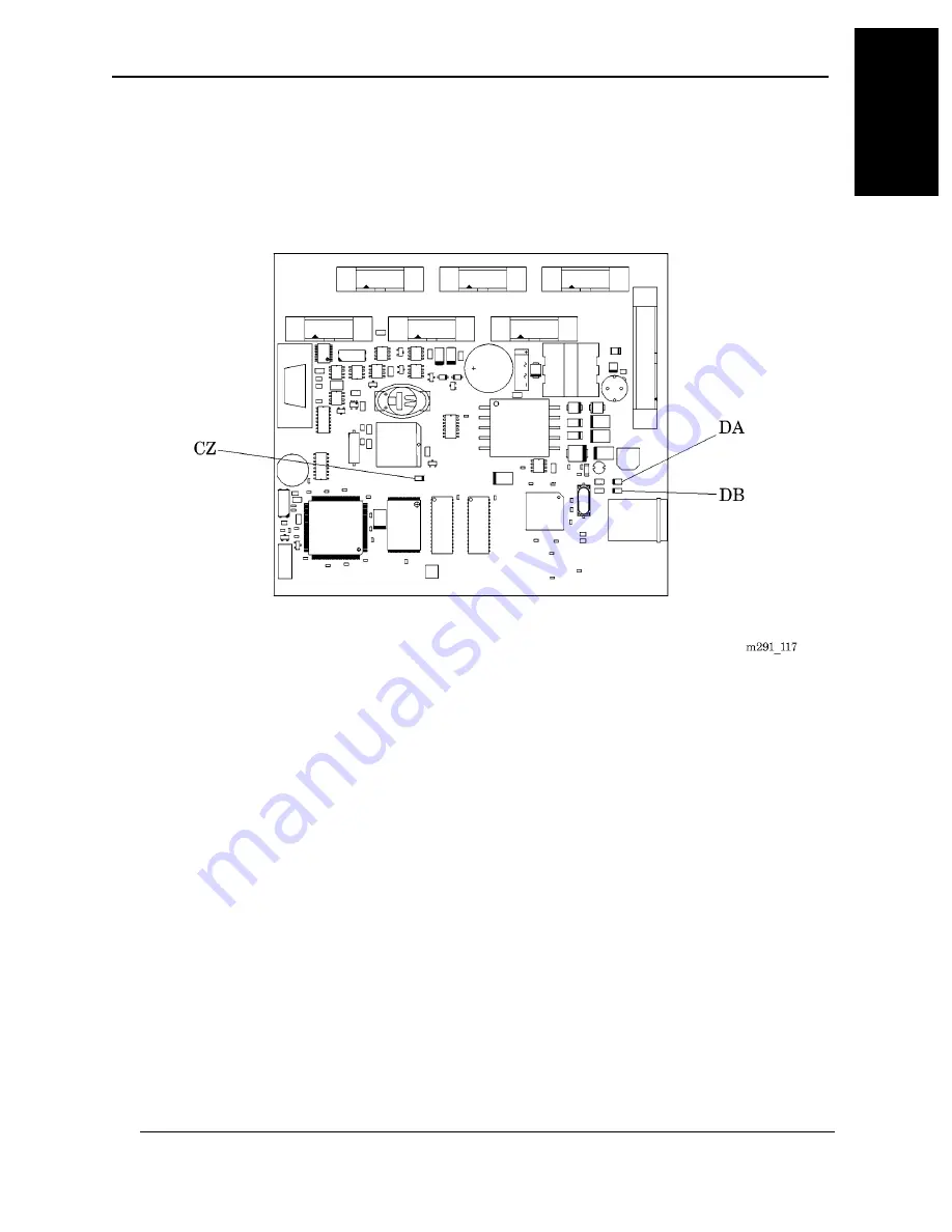
5. If the Network Communications Board is installed, check the three LEDs (see
figure 1-56 on page 1–113).
Figure 1-56. Network Communications Board
a. The first LED (CZ) indicates whether the software is operating correctly.
–
Steady flash indicates proper operation.
–
Solid ON or solid OFF indicates that the module has failed.
–
Rapid flashing indicates a software error.
MedPlus TotalAlert® Alarm Network Operation and Maintenance Manual (205728)
Page 1-113
Area Alarm Power-Up
Chapter 1: Introduction
1
Содержание MedPlus TotalAlert
Страница 13: ...Page xii MedPlus TotalAlert Alarm Network Operation and Maintenance Manual 205728 Table of Contents NOTES...
Страница 17: ...Page 1 4 MedPlus TotalAlert Alarm Network Operation and Maintenance Manual 205728 Chapter 1 Introduction NOTES...
Страница 203: ...Page 3 2 MedPlus TotalAlert Alarm Network Operation and Maintenance Manual 205728 Chapter 3 Theory of Operation NOTES...
Страница 289: ...Page 5 2 MedPlus TotalAlert Alarm Network Operation and Maintenance Manual 205728 Chapter 5 Parts List NOTES...
Страница 367: ...Page 7 2 MedPlus TotalAlert Alarm Network Operation and Maintenance Manual 205728 Chapter 7 Accessories NOTES...
Страница 370: ...Schematic Wiring Diagram Typical Local Alarm...
Страница 371: ...Schematic Wiring Diagram Typical Master Alarm...
Страница 372: ...Schematic Wiring Diagram Typical Master Alarm to Master Alarm...
Страница 373: ...Schematic Wiring Diagram Typical Area Alarm...
Страница 374: ...Schematic Wiring Diagram Typical Master Alarm to Three Area Alarm...
Страница 375: ...Schematic Wiring Diagram Typical Master Alarm to Six Area Alarm Combination...


