


Page 1-14
MedPlus TotalAlert® Alarm Network Operation and Maintenance Manual (205728)
Features
Chapter 1: Introduction
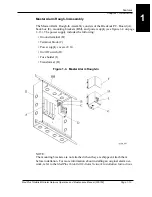
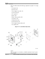
When installing the MedPlus TotalAlert® Alarm Network Conversion Kit, the
Breakout P.C. Board and the power supply assembly mount in the existing
alarm’s rough-in box. The conversion kit power supply mounts as single sub-
assembly, but uses the same internal components as the original power supply.
For more information about installing a conversion kit, refer to the
MedPlus
TotalAlert® Alarm Network Conversion Kits Installation Instructions
.
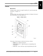
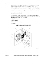
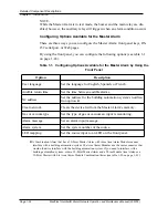
Master Alarm Front Panel
The Master Alarm Front Panel is designed to swing open from the rough-in
assembly (E) to easily install and service the alarm. The front panel consists of
the following (see figure 1-5 on page 1–14):
• Faceplate (M)
• Hinged door (L)
• Master Alarm Module (J)
• Lock (K)
Figure 1-5. Master Alarm Front Panel
Содержание MedPlus TotalAlert
Страница 13: ...Page xii MedPlus TotalAlert Alarm Network Operation and Maintenance Manual 205728 Table of Contents NOTES...
Страница 17: ...Page 1 4 MedPlus TotalAlert Alarm Network Operation and Maintenance Manual 205728 Chapter 1 Introduction NOTES...
Страница 203: ...Page 3 2 MedPlus TotalAlert Alarm Network Operation and Maintenance Manual 205728 Chapter 3 Theory of Operation NOTES...
Страница 289: ...Page 5 2 MedPlus TotalAlert Alarm Network Operation and Maintenance Manual 205728 Chapter 5 Parts List NOTES...
Страница 367: ...Page 7 2 MedPlus TotalAlert Alarm Network Operation and Maintenance Manual 205728 Chapter 7 Accessories NOTES...
Страница 370: ...Schematic Wiring Diagram Typical Local Alarm...
Страница 371: ...Schematic Wiring Diagram Typical Master Alarm...
Страница 372: ...Schematic Wiring Diagram Typical Master Alarm to Master Alarm...
Страница 373: ...Schematic Wiring Diagram Typical Area Alarm...
Страница 374: ...Schematic Wiring Diagram Typical Master Alarm to Three Area Alarm...
Страница 375: ...Schematic Wiring Diagram Typical Master Alarm to Six Area Alarm Combination...


