


Page 4-24
MedPlus TotalAlert® Alarm Network Operation and Maintenance Manual (205728)
Area Alarm Connector P.C. Board or Network Communications Board
Chapter 4: Removal, Replacement, and Adjustment Procedures
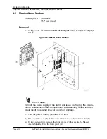
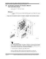
4.8
Area Alarm Connector P.C. Board or Network
Communications Board
Tools required:
5/32" hex wrench
Removal
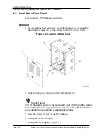
1. Using a 5/32" hex wrench, unlock the front panel (A) (see figure 4-9 on page
4–24).
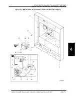
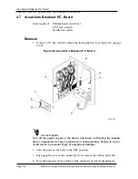
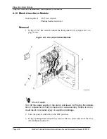
Figure 4-9. Area Alarm Connector P.C. Board or Network Communications Board
Shock Hazard:
Turn off the power supply in the alarm, and leave it off during the installa-
tion or replacement of any component or sub-assembly. Failure to do so
could result in personal injury or equipment damage.
2. Turn the power switch (H) to the OFF position.
The Area Alarm has either a Connector P.C. Board (D) or a Network
Communications Board (E) mounted to the back of the front panel (A).
Содержание MedPlus TotalAlert
Страница 13: ...Page xii MedPlus TotalAlert Alarm Network Operation and Maintenance Manual 205728 Table of Contents NOTES...
Страница 17: ...Page 1 4 MedPlus TotalAlert Alarm Network Operation and Maintenance Manual 205728 Chapter 1 Introduction NOTES...
Страница 203: ...Page 3 2 MedPlus TotalAlert Alarm Network Operation and Maintenance Manual 205728 Chapter 3 Theory of Operation NOTES...
Страница 289: ...Page 5 2 MedPlus TotalAlert Alarm Network Operation and Maintenance Manual 205728 Chapter 5 Parts List NOTES...
Страница 367: ...Page 7 2 MedPlus TotalAlert Alarm Network Operation and Maintenance Manual 205728 Chapter 7 Accessories NOTES...
Страница 370: ...Schematic Wiring Diagram Typical Local Alarm...
Страница 371: ...Schematic Wiring Diagram Typical Master Alarm...
Страница 372: ...Schematic Wiring Diagram Typical Master Alarm to Master Alarm...
Страница 373: ...Schematic Wiring Diagram Typical Area Alarm...
Страница 374: ...Schematic Wiring Diagram Typical Master Alarm to Three Area Alarm...
Страница 375: ...Schematic Wiring Diagram Typical Master Alarm to Six Area Alarm Combination...


